Continue to Site

Welcome to EDAboard.com

Welcome to our site! EDAboard.com is an international Electronics Discussion Forum focused on EDA software, circuits, schematics, books, theory, papers, asic, pld, 8051, DSP, Network, RF, Analog Design, PCB, Service Manuals... and a whole lot more! To participate you need to register. Registration is free. Click here to register now.

I need someone to confirm this simple circuit is correct

Status
Not open for further replies.

blitzkreigist

Newbie level 4
Joined
Apr 7, 2014
Messages
6
Helped
0
Reputation
0
Reaction score
0
Trophy points
1
Activity points
42
I am from computer engineering background and I vaguely remember circuits from one of my undergrad classes. I am making a simple circuit for one of my projects and I need to know if what I am doing is correct before blowing things up (again!).
IMG_20140407_115022.jpg

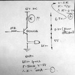
I have a 12V battery (7.2Ah). I am using that to power a LED whose specifications are 5mW, 5V. I am using PN2222A as the switch with base connected to 10K. I need to find the resistance in series which provides enough drop in voltage. So I designed the circuit as above. from (1) I = 1mA. so I derrived R as 6.7V/1mA = 6.7K Ohms. Is this correct?
 

Move the transistor down to be between the LED and ground, instead of between the LED and the resistor.

5V @ 1mA is sounds weird to me for an LED, so you might want to double check that. I'm used to red/green being in the 2V 2-20mA area and blue/white generally requiring more voltage and/or current than that.
 

Yeah, as it is to turn on the transistor you'll need a voltage equal to what the transistor needs plus what the LED needs. Move the transistor down and transistor will turn on with just the voltage needed to turn on the transistor.
 
Actually, the specifications for the LED are 5V, 5mW. So I just deduced that the current should be 5mW/5V = 1mA. I hope this is right
 

That might be intended for a pulsed configuration, where the led is controlled by a square wave with a frequency and duty cycle that overdrives the LED for a fraction of the second, then turns it off before it heats itself up enough to cause damage. The frequency is set to a rate that makes the LED appear to be continuously on to the human eye, I think thats around 60Hz+

1mA just sounds low to me, but it's your LED, I'll take your word for it. Just check the datasheet for stipulations of duty cycle, frequency, and peak current near that 5mW rating.
 

You know you might be right. I couldnt find the datasheet. I found these online. But **broken link removed** are the specs for led

Wavelength: 650nm
40 mA
Output Power: 5mW
Working Voltage: 5v
Operating Current: less than


So how do you think I should design my circuit now?
 

The only LED I can find with those specifications are red laser diodes. If that's what you have, the current is critical but I suspect you really have a normal indicator LED and the 5V is simply a guide to the kind of circuit that might power it. If I'm right, put the LED in the collector side as j33pn advised and ignoring the small saturation voltage of the transistor, use a resistor to set the current to about 10mA. So the resistor value is:
(supply voltage - LED forward voltage) / 0.01 with the result in Ohms.

Typically the forward voltage of a red indicator LED is about 1.6V.

Brian.
 

    V

    Points: 2
    Helpful Answer Positive Rating
DO NOT EVER buy no-namebrand LEDs that do not have a manufacturer's name, part number and detailed datasheet.
 

    V

    Points: 2
    Helpful Answer Positive Rating
650nm is red and 40mA@5V implies a built-in Constant current regulator with total power drawn at 200mW for a laser aperture power of 25mW

These are generally lot rejected parts ( something off spec) but sold very cheap, and still a bargain compared to a $150 industrial quality laser

5V is all you need at rated current.

Ask supplier, buyer beware.
 

    V

    Points: 2
    Helpful Answer Positive Rating
Unfortunately the laser dot diodes shown in the **broken link removed** are what I have.

unnamed.jpg

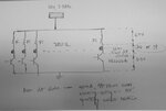
So I have 16 of these individual circuits in parallel all drawing from the same 12V,7.2Ah power source. Here is what I have done to calculate R for each circuit.
1. I am assuming the laser dot diodes need 5V across them to function properly
2. 0.3V voltage drop across the transistor while on (from datasheeet)
3. That leaves 6.7V across the resistor to be selected.
4. The specs for the laser dot diodes say operating current less then 40mA. So I am assuming 20mA. That brings R to 335 Ohms. Is that alright? whats the closest resistor value I can use

Also, all 16 lasers might not go off in parallel, Sometimes only one might be on, sometimes 7, sometimes all 16. Does it have any impact on current?

- - - Updated - - -

Should I place R individually for all 16 circuits or just one on top of all between power supply and ..err.. upper horizontal line
 

The nearest standard value resistor is 330 Ohms and yes, you need one for each laser.
I would urge caution though, laser diodes are not like nomal LEDs and they only operate over a small current range. Too little current and you get a very dim red glow, too much and they fry in an instant. It is quite likely though that those are not only laser diodes but also a current regulator built on the circuit board. Typically a laser diode also has a light sensor built inside it that allows an external circuit to optimize the current, that might account for the unusual voltage requirement they have. I would connect one with a 330 Ohm resistor and try it before risking the others.

Brian.
 

If you don't care about battery efficiency, that will work, otherwise You would be wiser to use a 6V battery or a 5V DC-DC converter.

All Red Lasers start working around 2V and run up to <3V and most Simple constant current (CC) with 2 transistors use 1.5~2V drop. Tolerance 5V +/-10% is expected, maybe +15% is ok.
 

Status
Not open for further replies.

Similar threads

Part and Inventory Search

Welcome to EDABoard.com

Sponsor

Back
Top