Continue to Site

Welcome to EDAboard.com

Welcome to our site! EDAboard.com is an international Electronics Discussion Forum focused on EDA software, circuits, schematics, books, theory, papers, asic, pld, 8051, DSP, Network, RF, Analog Design, PCB, Service Manuals... and a whole lot more! To participate you need to register. Registration is free. Click here to register now.

mosfet heat in buck converter

Status
Not open for further replies.

mshh

Full Member level 6
Joined
May 30, 2010
Messages
349
Helped
0
Reputation
0
Reaction score
0
Trophy points
1,296
Location
usa
Activity points
3,871
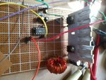
i am doing buck converter to transfer 50 watt of power at pwm of 100Khz but the mosfet heat increased with time when it works at 2 Amp however duty cycle is 50% power loses should be small , should i use bigger heat sink . i attached the circuit board with heat sink.
 

Attachments

  • 2014-04-03 14.25.18.jpg
    2014-04-03 14.25.18.jpg
    750.3 KB · Views: 149

Think about WHY should the power losses be small? If you've got a slow rise time on the mosfet gate, it will dissipate more power. If the mosfet has a high resistance it will dissipate more power. Further, that breadboard is probably not optimum; I'm sure you've got stray capacitance and inductances all over the place.
 

Further, that breadboard is probably not optimum; I'm sure you've got stray capacitance and inductances all over the place.
what is the optimum?
 

The first problem we can easily notice from picture is that you placed all components too far from themselves.

Another issue, are the long wires routing the board, which works almost as an antenna for frequencies even less than 100KHz.

When working with switched power supplies you must take special care on layout design.


+++
 
Kindly list your gate resistor value,Inductance,MOSFET part number Diode Part number etc.
 

here is the schematic it has every thing up on it.the inductor is T-94 26 and i used 50 turns around the core of two 25 turns connected in parallel . is the heat in converter transistors normal?
 

Attachments

  • circuitdaq.jpg
    circuitdaq.jpg
    195.7 KB · Views: 153

Kindly check your Gate pulse rise time and fall time it should be 2-5 % of your time period.your 22R gate resistor seems high for 100 KHz switching frequency and R3(Rge)
10K is quiet sufficient 1K seems quiet lower.
Why did you choose 100Khz switching frequency ?
higher the switching frequency complications will be more.
 
i think 100Khz is normal frequency for dc dc converter , what is your suggestion?
 

20-40 Khz is quiet sufficient for normal applications we need to increase the switching frequency only when we are very particular about reducing the inductor and capacitor size
as you go for 20 KHz you may have to use .250 to .350 MH inductance

If you are ok with it change the frequency to 20Khz and see the result.
 

I need high inductance and capacitance to reduce ripple in the circuit of my application , so if i reduced the frequency could i reduce inductance at the same time reduce ripple?
 

As you decrease switching frequency you need to increase the inductance and capacitance to reduce the ripple.
 

Status
Not open for further replies.

Similar threads

Part and Inventory Search

Welcome to EDABoard.com

Sponsor

Back
Top