Continue to Site
Follow along with the video below to see how to install our site as a web app on your home screen.
Note: This feature may not be available in some browsers.
PLC is Programmable Logic Controller?
i suggest:
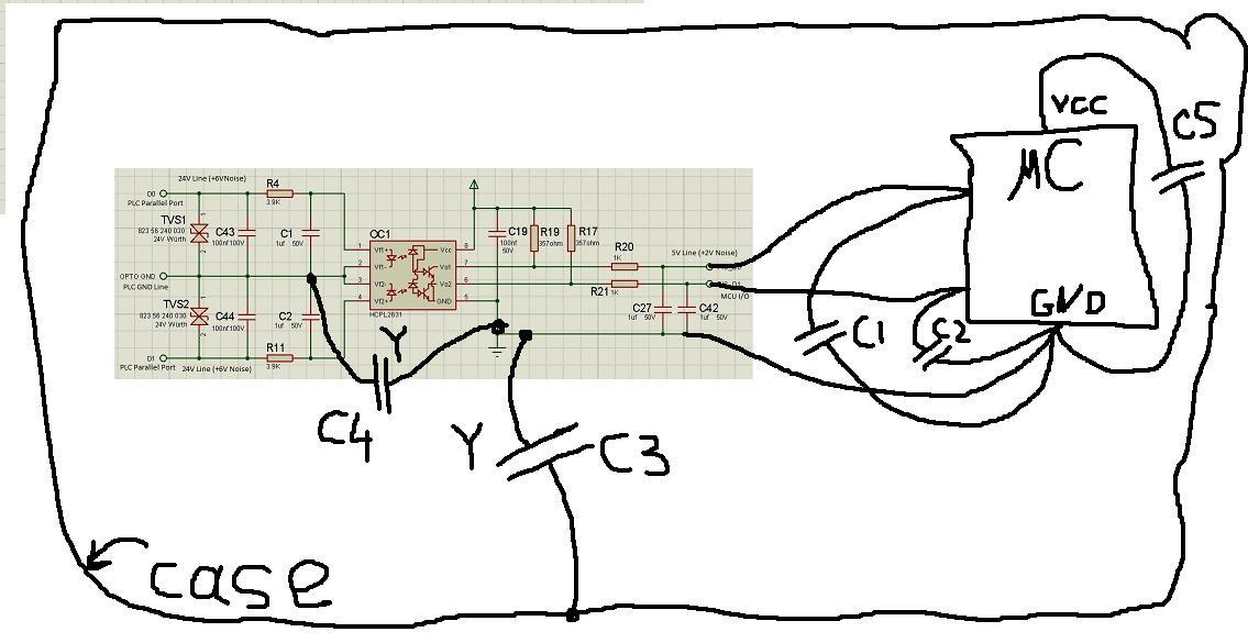
1 Y-cap C3 5n-200n
2 C1,C2,C5 capacitors NP0 (because of better freq char) 20n-100n connect directly to mc pins
3 (i have doubt about it) C4 - Y cap 5-200n
try it (1,2,3) separately and together

") . When shorten the length of the cable reset disseapeard.
. When shorten the length of the cable reset disseapeard. what you mean "every power line around card"? every Vcc? or Vcc and GND lines?I think my problem is differential noise. Because while problem occurs, every power line around card there is a noise. I really cant understand how can that noise passes all that filters and reset my MCU. Is it possible?
I agree about active filters.Interferences that reset a microcontroller will also exceed the linear voltage range of an active filter. I don't see how active filters can solve your problems.
Regarding common mode or differntial noise, it's difficult to determine likely interference pathes without a complete wiring diagram showing the external board connections. From similar cases, I guess that common mode is more plausible. But common mode noise will be converted into differential nosie in combination with asymmetrical signal termination, either on the board side or externally. And vice versa.
what you mean "every power line around card"? every Vcc? or Vcc and GND lines?
i think you problem is common mode noise. this kind of noise go thru parasitic capacinances. thats why it possible. to simplify understanding, imagine (or draw) line with changing with high dv/dt potential (created by valve) and all parts of you system, having parasitic capacitance to that line. all this capacitors forms loops. and interference currents flow thru that loops.
active filter just increase suppression ratio. you measured noise after EMI filter. now, using suppression ratio of that filter (from datasheet), calculate value of noise, which have to be at the input of filter. than ask yourself "is it really so big"?
- - - Updated - - -
I agree about active filters.
Yes, a complete wiring diagram showing the external board connections, including all metal cases and connected or not connected shields is very useful.
A trivial explanation would be that the reset is caused by your software design.