Continue to Site

Welcome to EDAboard.com

Welcome to our site! EDAboard.com is an international Electronics Discussion Forum focused on EDA software, circuits, schematics, books, theory, papers, asic, pld, 8051, DSP, Network, RF, Analog Design, PCB, Service Manuals... and a whole lot more! To participate you need to register. Registration is free. Click here to register now.

RC OSCILLATOR in pic16f877

Status
Not open for further replies.

amitaiwe

Member level 3
Joined
Feb 19, 2014
Messages
57
Helped
0
Reputation
0
Reaction score
0
Trophy points
6
Activity points
547
Hi,

In the pic16f877 data sheet is written:
"The RC oscillator
frequency is a function of the supply voltage, the resistor
(REXT) and capacitor (CEXT) values, and the operating
temperature. In addition to this, the oscillator
frequency will vary from unit to unit due to normal process
parameter variation."

The frequency value is derived from a capacitor and resistor values.
Q1. Is there any way that I can now approximately what will this frequency
be? I want to write a code in advance before I get the pic and
I want to know which value to enter into the SPBRG register so to
determine the baud rate. ( Baud Rate = FOSC/(4(SPBRG+1) )
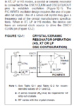
Q2. will the output frequency be fosc/4 as seen in the diagram?

Thanks, Amitai


Capture.PNG
 

Try this: https://en.wikipedia.org/wiki/RC_oscillator

The formula is in bold, first paragraph. There are other sources of resistance and capacitance as well, so the answer you get is not exact. Have you considered using a crystal instead?

John
 
Last edited:
Hi,

As the opening line of that paragraph says ' for timing insensitive applications ' so do not you think the USART module is timing sensitive?

If the USART is not accurately timed then its unlikely to communicate properly, so use a crystal or resonator at least.
 
I thought it might be easier with the RC osc, but now I see its less recommended
and I need a 8M frequency which I see in the list of available resonators.

Where is the output in the case of a crystal osc? it seems from the diagram bellow
that the osc2 output is used for the oscillation needs?

Thanks, Amitai
 

Attachments

  • Capture.PNG
    Capture.PNG
    43.3 KB · Views: 70

For UART work I would forget the RC oscillator, you need a speed accuracy of about 2% or better and unless you use temperature stabilized precision resistors and capacitors you might be 20% or more off target.

The crystal connects directly between OSC1 and OSC2 as shown in the diagram and you also need a capcitor from each of those pins to ground. For 8MHz I suggest 22pF capacitors should be used. Keep the crystal and capacitor wiring length to a minimum, ideally returning the ground side of the capacitors directly to the VSS pin.

If you want to use an external oscillator module rather than a crystal, connect it's output to OSC1 and leave OSC2 disconnected.

Brian.
 

Thank again,
It seems that I will use the internal crystal osc.
I understand from the diagram that 2 capacitors need to be added and were.
I'm still not certain where is the output of the clock (from the pic outwards to another component),
is it from the pin OSC2? (the same pin which the crystal is connected to in the diagram between RS and RF?)

Amitai
 

Thanks a lot,
A 3-pin indeed makes life easy..
Is the pin OSC2 which is connected to the resonator the same pin which functions as an output?

Amitai
 

You can under some circumstances use it as an output but only if you ensure it has very little loading on it. If you need the clock to drive other parts of you circuit, use a high impedance buffer fed from OSC2 to isolate your circuit from the PIC oscillator circuits. A better solution would be to use an external 8MHz oscillator module which would be capable of driving several loads, then connecting it to OSC1 as I mentioned earlier.

When configured to use the internal oscillator with a crystal or resonator the output signal is connected internally to the workings of the PIC. All you do is provide the crystal/resonator and the PIC does the rest for you. In other words, it isn't a 'stand alone' oscillator you have to feed back into the PIC, the connection is already inside the IC.

Brian.
 

Thank again,
It seems that I will use the internal crystal osc.
I understand from the diagram that 2 capacitors need to be added and were.
I'm still not certain where is the output of the clock (from the pic outwards to another component),
is it from the pin OSC2? (the same pin which the crystal is connected to in the diagram between RS and RF?)

Amitai


Hi,

You imply that you want to use the frequency of the oscillator for other parts of a circuit; as said when using a crystal or resonator there is no direct clock output.

What you can do, if your other circuit only needs a square wave below 100K ( with a 8mhz oscillator) is to use the 877s PWM function, which once started will run without affecting any other program code.

Also consider other 40 pin chips like the 16F887 or the 18F4520 which are basically pin identical to the 877A, but have a inbuilt oscillator thats good for Usart use, but also has a direct Clock Output (Fosc/4) on OSC2 pin.
 

I thought about choosing a different PIC with an internal osc, but I'm shortened in
time and can't replace the PIC16f877 which I have ordered.

what do you mean by: " 100K ( with a 8mhz oscillator) " ?
I need a clk of 8M to be derived to component. You mean that the PWM divides the
frequency and therefor the output can only be smaller then 8M ?

Amitai

Hi,

The 877 chips PMW output can only go up to about 100k, when it uses a 8mhz crystal, where it get its timebase from, so that would be unsuitable for you.

Those other chips would also be unsuitable, as the oscillator signal they give out is not the Oscillators frequency , Fosc, of 8mhz but the system clock frequency which is Fosc/4 = 2mhz.

You only way to get 8mhz for both the 877 and your other devices (?) is by buying a ready made 8mhz crystal oscillator module or making your own, many examples on the web, though a ready made one is quite cheap.
 
I have another question, also about this PIC:
when I use the SPI protocol do I need to check that transmitting has occurred via PIR1, SSPIF,
same as in the UART where I need to check PIR1, TXIF ?
Thanks, Amitai

Capture.PNG
 

Thanks!
I want to communicate between the pic and a LDC1OOO of TI which communicates via SPI,
and I want to be sure that I understand correctly a few things:
1. does the CSB pin of the LDC need configuration or that it automatically changes when communication is happening?
2. for knowing that a transmission from the LDC to the PIC has finished is the BF check enough or I need to check somehow in the LDC's end for ending of transmission?

Amitai
 

Attachments

  • ldc1000.pdf
    1.6 MB · Views: 64

Thanks!
I want to communicate between the pic and a LDC1OOO of TI which communicates via SPI,
and I want to be sure that I understand correctly a few things:
1. does the CSB pin of the LDC need configuration or that it automatically changes when communication is happening?
2. for knowing that a transmission from the LDC to the PIC has finished is the BF check enough or I need to check somehow in the LDC's end for ending of transmission?

Amitai

Hi,

Have never used the TI chips so no idea how easy it is to connect those two different micro families, though the point of protocols like SPI or I2c is that it should make it easy
Seems plenty of info on TIs site
https://www.ti.com/lit/an/snaa213/snaa213.pdf

Sure someone like Betwixt with his much wider experience will be able to help you here.
 
Status
Not open for further replies.

Similar threads

Part and Inventory Search

Welcome to EDABoard.com

Sponsor

Back
Top