Continue to Site

Welcome to EDAboard.com

Welcome to our site! EDAboard.com is an international Electronics Discussion Forum focused on EDA software, circuits, schematics, books, theory, papers, asic, pld, 8051, DSP, Network, RF, Analog Design, PCB, Service Manuals... and a whole lot more! To participate you need to register. Registration is free. Click here to register now.

Would You Expect this Op-Amp to Amplify Small Voltages?

Status
Not open for further replies.

deepsatchel

Newbie level 6
Joined
Jan 5, 2014
Messages
11
Helped
0
Reputation
0
Reaction score
0
Trophy points
1
Activity points
93
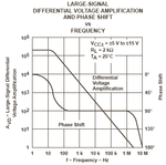
I am attempting to amplify an AC input signal in the ± 15 µV ballpark. Would you expect this op amp to rectify the signal? I see the maximum input figure, but no minimum figure! Does this op amp not "see" small signals?

**broken link removed**

How can I be sure that a given op amp will respond to ~ µV differentials?
 

The very old Japanese dual opamp has a typical voltage gain of 110dB (300,000 times) from DC to about 10Hz.
If it is biased properly it can amplify 15uV to 4.5V but it will have a lot of noise.
Is a rolloff at 10Hz good enough? What is the signal?
 
The signal being rectified is the extremely flat (in spectral density) avalanche breakdown noise from a zener diode. If I use a number of these op amps in series, each with a relatively small gain of around 10x, could I bring the noise (from the diode) to audio line level without introducing as much of the undesired opamp noise?

Also, how can we be sure that the op amp is sensitive enough to actually amplify a difference of several µV on its inputs?

edit: the rolloff at 10hz is fine for me because this is an audio application.

edit #2: woops, are you saying that 10hz is the top of its bandwidth? Where does it say that in the datasheet? I need to read more carefully before I buy stuff. :shock:

edit #3: Sorry, I got excited, and also didn't understand the GBW figure. So, at a gain of 300,000 the bandwidth is 0-10Hz. Is it correct that if I did 5 amplifications, each with a gain of 10, I could arrive at 15 µV * 10^5 = 1.5 V and each amplifier stage would have a bandwidth of 0-1.5MHz?
 
Last edited:

The signal being rectified is the extremely flat (in spectral density) avalanche breakdown noise from a zener diode. If I use a number of these op amps in series, each with a relatively small gain of around 10x, could I bring the noise (from the diode) to audio line level without introducing as much of the undesired opamp noise?

Also, how can we be sure that the op amp is sensitive enough to actually amplify a difference of several µV on its inputs?

edit: the rolloff at 10hz is fine for me because this is an audio application.

edit #2: woops, are you saying that 10hz is the top of its bandwidth? Where does it say that in the datasheet? I need to read more carefully before I buy stuff. :shock:
Why do you think your noise source has such a low signal level?
The datasheet for all opamps (except the Japanese one you selected) shows a graph of its frequency response vs its gain. The TL07x audio opamp has a gain of about 200,000 up to about 20Hz then its gain is reduced 6dB per octave so at 3MHz (where the phase shift almost causes oscillation when it has negative feedback) its gain is less than 1 so it does not oscillate.

There are many noise generators shown in Google made with a zener diode and a single opamp with a gain of only 100 (NOT 300,000). Then an audio opamp can have a bandwidth to 32kHz.
 

Attachments

  • TL07x cutoff frequency.PNG
    TL07x cutoff frequency.PNG
    17.8 KB · Views: 100

I got the signal level estimate from some study a member of diyaudio.com did (attached). I bought a 1N5996 Zener for the job but I don't remember why exactly. All I know is that I wrote down that I expected 15uV for the output on one of my scribbles.

So maybe I should just buy different zener and op amps. Seems like these things I have are not ideal for what I'm trying to do.
 

Attachments

  • noise_measurements_1_4.txt
    14.4 KB · Views: 67

I don't know why most circuits have a gain of 100 but the circuit you found has a gain of 1156.
About 35 years ago I made a pink noise generator with a digital psuedo-random noise IC. Its noise sounded random then repeated every 45 seconds.
I calibrated its pink-filter against a very expensive professional pink noise generator.

Try your circuit with your zener diode and dual opamp. Do you want white noise or pink noise?
 

Pink noise is the goal. I was thinking of using the filter stage from Rod Elliot's design shown **broken link removed** after the white noise is made.

If I were going to use just the components I have, how would you recommend biasing the opamp inputs? I'm using a single-ended supply (9V battery), and I also have a rail splitter providing a 4.5V reference.
 

Rod Elliot's circuit has a gain of 101 x 2.46= 249 at high audio frequencies and a gain of 101 x 101= 10,201 at very low frequencies.
Your circuit will have half his supply voltage so maybe your gain must be a little less. Even if your oscilloscope is very good it will be difficult to see clipping.

Since opamps have very low input bias current then the rail splitter resistors can have high values (220k each) then have a pretty big filter capacitor for the half voltage.

EDIT: Fixed math error
 
Last edited:
Thanks for that circuit analysis. Could you elaborate a little bit about how you came up with the 2.46 gain figure for the pink-filter at high frequencies?

I seem to be having some problem with this simple circuit I'm building. On the output of the opamp before the output capacitor, I read 8.5V -- not 9.02V, which should be saturation. Do you know what might be going on here?

6801128300_1388934749.png
 

The pink filter at the highest frequency has 4 feedback resistors in parallel making 14.6k. Then the gain of that opamp is 1+ (14.6k/10k)= 2.46 times.
Your opamp is simply a follower at DC. Its output should be +4.5V plus or minus a few millivolts of input offset voltage.
With a 9V supply and no load, the output of most opamps saturates at about 1.2V and 7.8V. Your 1k feedback resistor is a load so its output probably saturates at +1.5V and +7.5V.

1) Your inverting opamp has an input impedance of only 100 ohms that SHORTS the signal you want. If the opamp is non-inverting then its input impedance can be 100k or even 1M so it does not load down and reduce the signal at all.

2) Any fluctuation of your 9V rail is amplified by the opamp. Swap the positions of the zener diode and the resistor that powers it so that the opamp amplifies only the signal from the zener diode.

3) The 1k feedback resistor value is so low that most opamps might have difficulty driving it. If the signal has a peak voltage of 3V then the peak current in the feedback resistor and from the output of the opamp is 3mA.

4) The 200k resistor in series with the (+) input of the opamp is not needed and is not wanted. It should be a piece of wire since the opamp has a gain of only 1 at DC.
 
I changed to a non-inverting configuration, increased the feedback resistors to 10k and 1k, and swapped the zener and its current resistor. Unfortunately my antique oscilloscope broke recently, but my multimeter is telling me that my output is 4.5V DC with some amount of AC ripple -- exactly what I need!

I drew up another picture to represent my new configuration. Does this look like it should work or is my meter lying to me?

9225518400_1388939763.png
 

You certainly DO NOT need the 200k resistor. Replace it with a piece of wire.
The 1k resistor should have a series capacitor to ground, not to 4.5V.
The gain is only 11 which is not enough.
 

Oh, I thought I would need some resistance after the noise source so that it does not become loaded down. Is this not an issue for non-inverting opamps?

If I'm not utilizing my 4.5V reference to bias anything, how do I make sure I'm not losing the negative half of my noise signal?
 
Last edited:

Oh, I thought I would need some resistance after the noise source so that it does not become loaded down. Is this not an issue for non-inverting opamps?
The datasheet of the Japanese NJM4580 dual opamp you were thinking about does not mention its input impedance.
The lousy old 741 opamp has an input impedance of typically 1M ohm.
The input impedance of a TL07x audio opamp is 1 million million ohms. (One followed by 12 zeros).

If I'm not utilizing my 4.5V reference to bias anything, how do I make sure I'm not losing the negative half of my noise signal?
I forgot that the (+) input of the opamp must be biased at +4.5V through a high value resistor (100k is fine). Then the zener diode will be driving the resistor that powers it parallel with the 100k biasing resistor parallel with the 1M or higher input impedance of the opamp.
 

Attachments

  • White noise generator.png
    White noise generator.png
    6.4 KB · Views: 128
Thanks for that update of the schematic. I've built it, but can't get a good result. One thing I noticed is that there's a pretty decent voltage drop across the 100k resistor. If the rail side is 4.50V the other side is around 4.40V. This is suggestive to me that the opamp possibly has a low input impedance, loading down the source, and may be part of the problem. Not sure if this detective work is completely valid though.

So, if I built that schematic exactly and it doesn't work, should I just move on and buy some mainstream opamp and go from there? The lack of detail in the datasheet leaves open too many variables.
 

One thing I noticed is that there's a pretty decent voltage drop across the 100k resistor. If the rail side is 4.50V the other side is around 4.40V.
That's not right. The end of the 100K resistor that's connected to the opamp should be slightly more positive than the other end. According to the opamp's datasheet, it's input bias current is typically 100nA, maximum 500nA, so the voltage drop across the 100K resistor should be typically 10mV, maximum 50mV.

This is suggestive to me that the opamp possibly has a low input impedance, loading down the source...
No, that's not the problem.

I suspect you did the measurements by connecting one probe of the multimeter to the negative terminal of the battery, and the other probe to first one end of the resistor, then the other. In that case, it's the input impedance of the meter that's loading down the circuit and causing misleading readings.

To get a more honest measurement of the voltage across the 100K resistor, measure it directly, with one probe of the meter connected to each end of the resistor.

The lack of detail in the datasheet leaves open too many variables.
What lack of detail? It looks pretty comprehensive to me. I didn't see input impedance mentioned, but that's almost irrelevant for most applications.

BTW, according to their datasheets, the NJM4580 has lower distortion, lower noise and better bandwidth than the TL071. Looks good to me.
 
Hey, thanks for the info godfreyl! As you suggested I measured the resistor leg to leg; I see a voltage drop of 0.0mV. Does this mean perhaps that for some reason no current is being drawn into the input?
 

The NJM4580 dual opamp is (was?) also made by Texas Instruments called the RC4580. Another feature of it is that it will work from a supply as low as only 4V.
It has PNP input transistors so their bias current increases the voltage a little of the input pin when the series bias resistor is 100k.
The IC was made to be the RIAA preamp for record players with a moving magnet cartridge (remember them?).
 

It has PNP input transistors so their bias current increases the voltage a little of the input pin when the series bias resistor is 100k.


If I don't see that voltage increase, what could that indicate?
 

If I don't see that voltage increase, what could that indicate?
It indicates that your meter or oscilloscope is not sensitive enough to measure the tiny voltage increase.
The typical input bias current is only 100nA which is 0.0000001A. The voltage across the 100k bias resistor is 10mV which is 0.01V. Who cares?
 

Status
Not open for further replies.

Similar threads

Part and Inventory Search

Welcome to EDABoard.com

Sponsor

Back
Top