Continue to Site

Welcome to EDAboard.com

Welcome to our site! EDAboard.com is an international Electronics Discussion Forum focused on EDA software, circuits, schematics, books, theory, papers, asic, pld, 8051, DSP, Network, RF, Analog Design, PCB, Service Manuals... and a whole lot more! To participate you need to register. Registration is free. Click here to register now.

Diode with floating terminal

Status
Not open for further replies.

vinodquilon

Full Member level 3
Joined
Oct 24, 2009
Messages
158
Helped
2
Reputation
4
Reaction score
2
Trophy points
1,298
Activity points
2,558
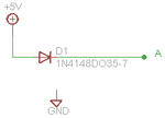
Consider the circuit arrangement shown in the attachment.
If I connect a MM in voltmeter mode at floating terminal A, What would be the reading on the voltmeter?
If I terminate the floating A terminal with a 10K resistor to GND, What would be the change in reading shown?
 

Attachments

  • diode float.png
    diode float.png
    1.4 KB · Views: 195

that depends on the Rin of your multimeter ad the diode and the volage source. If the diode does not conduct current you will measure an electric field.
 
Increasing the current in the diode, starting from 0 A, the voltage drop across the diode will increase, until it will reach approx 0.6/0.7 after that (relative) big increases in the current will cause small increases in the voltage drop.
Due to this, since the MM has a quite high input impedance you shoud see a voltage drop close to zero, then the output voltage will approach the input voltage Vo≈Vi-0.6. Closing the cathode to ground using a 10K resistor you should see a variation of approx 0.6V, that is Vo≈Vi-0.6
 

Assuming the DMM input impedance is 1 M, the current will be 5uA vs the 10K load of 500uA.
Looking up Vf on the log curve of the 1n4148 on p2 of **broken link removed**

I get Vf {5 ~ 500uA}= { <0.4V ~ 0.6V}
 

that depends on the Rin of your multimeter ad the diode and the volage source. If the diode does not conduct current you will measure an electric field.

What you mean by 'measure an electric field' ? Is it ac voltage at floating terminal ?

- - - Updated - - -

Here is my interpretation considering the case of non-ideal diode,

CASE 1(without 10K)-- Depending on the output impedance of DC voltage source and the input impedance of the MM, the drop across the diode is not enough to turn it ON. And the MM will reads electric filed at floating terminal. And it will be high depending on the neutral to earth voltage of ac supply distribution to the voltage source (if above 1V).

CASE 2(with 10K)--The effect of high input impedance of MM get reduced due to parallel 10K. In this case diode conducts and the output at non-floating terminal will be [5V-(forward diode drop)].
 

vinodquilon,

What you mean by 'measure an electric field' ? Is it ac voltage at floating terminal ?

You are right to wonder about measuring the electric field. A voltmeter measures voltage, not electric fields. It does this by measuring the current existing through its internal impedance, and translating that value into voltage.

CASE 1(without 10K)-- Depending on the output impedance of DC voltage source and the input impedance of the MM, the drop across the diode is not enough to turn it ON. And the MM will reads electric filed at floating terminal. And it will be high depending on the neutral to earth voltage of ac supply distribution to the voltage source (if above 1V).

A diode is always turned on when you forward bias it like you are doing when you connect a resistor or a voltmeter to the floating end. The current becomes significant when the voltage across the diode is at or above 0.6 or0.7 volts for a silicon diode. But, a small current still exists at any small forward voltage across the diode above zero. Connecting the voltmeter in series with the diode will cause the current to be 5 volts divided by the sum of the diode resistance and the meter resistance. The current will energize the voltmeter to a particular voltage depending on the resistance of the voltmeter. The resistance of the diode will vary with the current existing through it according to Schokley's diode equation. You can get a value of the current by imposing a load line on the diode curve.

CASE 2(with 10K)--The effect of high input impedance of MM get reduced due to parallel 10K. In this case diode conducts and the output at non-floating terminal will be [5V-(forward diode drop)].

In this case, less resistance is in series with the diode, and the current in the diode will increase. The voltmeter current will be shared with the 10k resistance, so if you know can figure out the current of the diode and know the resistance of the meter, you can determine the voltage it will read.

Ratch
 
What you mean by 'measure an electric field' ? Is it ac voltage at floating terminal ?

- - - Updated - - -

Here is my interpretation considering the case of non-ideal diode,

CASE 1(without 10K)-- Depending on the output impedance of DC voltage source and the input impedance of the MM, the drop across the diode is not enough to turn it ON. And the MM will reads electric filed at floating terminal. And it will be high depending on the neutral to earth voltage of ac supply distribution to the voltage source (if above 1V).

CASE 2(with 10K)--The effect of high input impedance of MM get reduced due to parallel 10K. In this case diode conducts and the output at non-floating terminal will be [5V-(forward diode drop)].

Yeah true, but in case 1, just assume the diode as diode and look its characteristics, for the current which the series resistor (MM voltmeter) could make flow
find the diode voltage and do as case 2..
There is no direct voltage answers for case 1 because we wont measure the forward voltage drop of diode for such a low current.....
 

Venkadesh_M,

Yeah true, but in case 1, just assume the diode as diode and look its characteristics, for the current which the series resistor (MM voltmeter) could make flow
find the diode voltage and do as case 2..

Hard to do, since the current in a diode varies in a nonlinear exponential way. it has to solved using incremental methods or graphically with a load line.

There is no direct voltage answers for case 1 because we wont measure the forward voltage drop of diode for such a low current.....

That depends of the sensitivity of the equipment, doesn't it.

Ratch
 

Venkadesh_M,


Hard to do, since the current in a diode varies in a nonlinear exponential way. it has to solved using incremental methods or graphically with a load line.


That depends of the sensitivity of the equipment, doesn't it.

Ratch

The easiest way of measuring is connecting a multimeter(known Resistance) in series(A measuring multimeter can disturb the voltage)......
 

Venkadesh_M,

The easiest way of measuring is connecting a multimeter(known Resistance) in series(A measuring multimeter can disturb the voltage)......

Measure what? What function, voltage or current of the multimeter? Certainly the multimeter will disturb the reading, unless the diode has enough current existing in it to lower its resistance to an insignificant value with respect to the voltmeter.

Ratch
 

Venkadesh_M,


Measure what? What function, voltage or current of the multimeter? Certainly the multimeter will disturb the reading, unless the diode has enough current existing in it to lower its resistance to an insignificant value with respect to the voltmeter.

Ratch
To know the voltage on multimeter terminals...
 

For all you people who think I talk bullshit, try it first. This question was asked on a dutch forum and because every body said something different I and some others did extended tests on this.
I used electrometers, tube voltmeters, analog meters, digital meters, so a Rin from 10k/V upto > 10 GOhm. Try this your self and you will see what I mean. I think to many people believe spice and forget that it is much faster to measure this then asking it on a forum ;-) I used a 5VAC source and a diode bridge and measured between the + and - of the bridge. Some meters with a very high Rin measured more as 160VDC. A 10M DCV meter measures about the VAC in DC mode. A true RMS AC+DC meter and enough load will give correct readings. But the signal is 100Hz pulsed DC. I also monitored it with a scope (with very high Z, low C probes) and the voltage only looks like the tekst books when the diodebridge is loaded enough.

The 0.6V drop is also a simplification from the textbooks. For instance a 1N4007 has a voltdrop that varies from zero Volt upto over 1V at full current. I tested this (and some other diodes on a Tek 576 curvetracer upto 10A. But if you run it at more as 1A (it exploded at 10A and > 150 degrees Celcius) the volt change due to temperature rise becomes very important in the result.
 
Hi PA4TIM
The problem is here all are talking theoretically but you are talking practically, I think you meant #6,
summarizing....
A voltmeter is works as it to measure the voltage across its ends but with a very high resistance it able to measure the electric field (It doesnt discharges the initial field but a ordinary MM collapses the field and start measuring the voltage)...
The 160V you measured is the initial field, try loading it through a switch and measuring it after switch disconnected..
 

Assuming the DMM input impedance is 1 M, the current will be 5uA vs the 10K load of 500uA.
Looking up Vf on the log curve of the 1n4148 on p2 of **broken link removed**

I get Vf {5 ~ 500uA}= { <0.4V ~ 0.6V}


THE CHANGE in reading is just great than 200 mV. There is no guesswork with these assumptions and specs.
 

Status
Not open for further replies.

Similar threads

Part and Inventory Search

Welcome to EDABoard.com

Sponsor

Back
Top