Continue to Site

Welcome to EDAboard.com

Welcome to our site! EDAboard.com is an international Electronics Discussion Forum focused on EDA software, circuits, schematics, books, theory, papers, asic, pld, 8051, DSP, Network, RF, Analog Design, PCB, Service Manuals... and a whole lot more! To participate you need to register. Registration is free. Click here to register now.

REPLACEMENT of BJT by MOSFET

Status
Not open for further replies.

bmodi700

Junior Member level 2
Joined
Jul 18, 2013
Messages
22
Helped
0
Reputation
0
Reaction score
0
Trophy points
1
Activity points
142
Hello all,
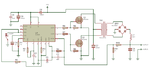
I have 2 transistor in my circuit (dc to ac converter)

1)TIP41A(npn)
2)TIP42A(pnp)

i want to replace this by N-mos and P-mos
which MOSFET i can use??
waiting reply
 

can you post the schematic of the circuit..
here is the schematic ..i want to use mosfet instead of transistor Q1 and Q2..
555dcac.gif
 

It is a horrible square-wave inverter with many voltage losses and very low output power.

With a 6V supply, the output of the 555 swings from about 0.2V to 4.6V when it has low output current.
The TIP41 and TIP42 each need a base-emitter voltage that is 0.7V.
Then the output voltage swing is from about 0.9V to 3.9V which is 3.0V peak to peak.

When the load power is 0.4W then the output swing of the 555 is from 1.5V to 4.4V and the base-emitter voltage for each transistor is 0.9V then the output swing is from 2.8V to 3.5V which is only 0.7V.
The voltage regulation is awful since it changes from 3V p-p to 0.7V p-p with a weak little load connected.

Ordinary Mosfets need up to 10V gate-source voltage EACH then the 555 cannot drive them.


SO can you suggest me any other circuit ?
 

here is the schematic ..i want to use mosfet instead of transistor Q1 and Q2..
Hi
If you use mosfet , you have to use totem pole to drive it in a right condition so using BJT is unavoidable .
It is a horrible square-wave inverter with many voltage losses and very low output power.
Hit to the point !
SO can you suggest me any other circuit ?
Yes there are many other ways for this purpose . perhaps using a push pull converter based on SG3526 ( if you are looking for square wave of course )

Best Wishes
Goldsmith
 

simple-100W-inverter-circuit.png555dcac.gif

guys which one is better...555 one or CD4047???
my ultimate aim is to to glow 20w CFL bulb...
i also don't want to glow it by full intensity
so which one i can use of better result???

-waiting for reply
 

4047 definitively. It gives exact 50% duty cycle while 555 is not.
 
The Mickey Mouse square-wave inverter circuit with the CD4047 has "shoot-through" where both Mosfets are turned on for a moment each time they switch and short-circuit the 12V with a very high current spike.
 
The Mickey Mouse square-wave inverter circuit with the CD4047 has "shoot-through" where both Mosfets are turned on for a moment each time they switch and short-circuit the 12V with a very high current spike.

Actually though a 'shoot-thru' situation might exist, i don't think it'll be catastrophic in this circuit since the transformer T1 is in the path and the MOSFETs aren't actually connected in series across the supply but rather in parallel.

The critical factors in this circuit is the design/ specs of the transformer ... i.e. the primary inductance & saturation currents , and the frequency of operation. Nothing has been said about these, yet they are the most critical for proper operation.

And of course - there is NO mention of regulation/ feedback/ control etc etc.
 
Last edited:
use this ckt sg3525 based pwm inverter. o/p diodes can be omitted
 

Attachments

  • 4566970400_1379271846.png
    4566970400_1379271846.png
    42.2 KB · Views: 123

Status
Not open for further replies.

Similar threads

Part and Inventory Search

Welcome to EDABoard.com

Sponsor

Back
Top