Continue to Site

Welcome to EDAboard.com

Welcome to our site! EDAboard.com is an international Electronics Discussion Forum focused on EDA software, circuits, schematics, books, theory, papers, asic, pld, 8051, DSP, Network, RF, Analog Design, PCB, Service Manuals... and a whole lot more! To participate you need to register. Registration is free. Click here to register now.

Unbalanced "phantom" power

Status
Not open for further replies.

oneoldude

Junior Member level 1
Joined
Aug 12, 2013
Messages
16
Helped
0
Reputation
0
Reaction score
0
Trophy points
1
Location
Florida, USA
Activity points
257
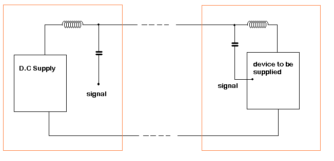
I would like to use an unbalanced two conductor interface to power an unbalanced buffer or amplifier and be able to pull off the AC signal to feed an ADC all using two conductors. PS could be anything from 9V to 15V and current draw anywhere from 3 mA to 30 mA (not at the same time this is for different possible circuits).

I was thinking it would be like 2/3 of a P48 but at a different voltage. I would like to avoid a 3 pin connector and 3 wire cable.

I have tried to sim this idea with no success at all. So i clearly do not understand the problems. Is it even possible?

Thanks
 

You do not say what sort of signal you are sending down the line. The way to do it is to have your two DC lines and send two antiphase signals down each one. So at the reception end you just use a amplifier with a differential input. the difficult part is filtering the DC lines without putting too much load on the signal driving source. This was done with iron based transformers with antiphased windings. It is used in every telephone!
Frank
 

chuckey,

Yes, balanced systems have been around since the advent of the telephone and are virtually exclusively used by the pro audio community. But there is often more than one way to skin a cat.

I am working on a measurement mic for at home measurement of loudspeakers. I want the simplest system possible so that I do not need to use balanced pro audio gear. I have balanced stuff but do not like using it. Mine does not even let me bypass the tone controls and centered pots or sliders do not necessarily mean flat.

I have routinely used 40 ft unbalanced cables with no appreciable noise but the mic capsules can't handle the cable capacitance and start to roll off the high end. So I figured a buffer would be ideal.

I have XLR connectors to do three wire powered unbalanced mics but there is always a possibility of using one of those with a pro audio system with disastrous results. So a simple two wire system with BNC connectors should prevent all confusion. It seems that is what the super high quality industrial measurement guys use with constant current loop design. I don't want to go quite that far. Heck, I might even use high quality RCA connectors, I have plenty of them.

I have been researching the web and found an AD app note that may be a solution. I have it simmed in LTS and it works. Optimizing it is another thing entirely. Any help along that line is greatly appreciated.

Here is the app note: **broken link removed**

Thanks
 
Last edited:

Certainly you can use a capacitors to block the DC and allow the AC signal to pass to the amplifier inputs and outputs. Then you would need an inductor or (for low currents) an RC filter to suppress the AC from appearing at the amplifier's power pin. That sort of thing has often been done to transfer power and signal over the same line.
 

The term "phantom power" is closely related to balanced signal transmission. Unbalanced signals with superimposed power supply are however widely used. Most electret microcpohones respectively PC soundcard microphone inputs are using it, also antenna amplifiers and satellite LNBs. For low supply power and low signal frequencies, RC bias-tees are a simple and straightforward solution.
 
Hi oneoldude
do you mean something like this ?

Rafan


Hi oneoldude
do you mean something like this ?

Rafan

Sort of. This is what I had in mind.

V2 is an ECM mic. Green is input. Yellow is taken off of RL.

CC is the cable capacitance and that is where the connection is made between PS and buffer. I am using 30p per ft for 100 ft even though I will probably only use about 40 ft of cable. Note no rolloff at HF.

Balancing and optimizing R6, R7 and C3 are problematical because changes there can even affect the input!

Also, R8 is a stopper to prevent instability. But even relatively small increases there knock down the output substantially.

Until I get those problems worked out I cannot begin to optimize C2 and C5. I would like to get f3 on the low end around 3-7 Hz so that I am straight as a string from 20-20K.

BTW I got the basic idea from the pdf I pointed to above.

If I learn how to handle this powering method it might be a good idea to use an OPA that is stable into capacitive loads like a cable tv driver. I am not going to listen to this or record it either. It is only for measurement so stability and accuracy are the game.

Here is what I have so far:

2wire ECM mic buffer.PNG
 
Last edited:

Also, R8 is a stopper to prevent instability. But even relatively small increases there knock down the output substantially.
Not understandable at all. I presume you know that most audio systems are working fine with a 200 to 600 ohms impedance level. Driver impedance for long cables should be a bit lower. The 0.1 miiliohm value you put in for R8 isn't but ridiculous. I guess, you'll net at least some 10 ohms to achieve stability with a emitter follower or OP buffer. That's good for 100 kHz and more bandwidth, so what's the problem? There will be a small voltage drop caused by the R8 to R6||R7 voltage divider, but it's constant and can be well compensated.

All in all the problem can be easily solved and has been already a thousand times.
 

oneoldude
Re: "I would like to get f3 on the low end around 3-7 Hz so that I am straight as a string from 20-20K."

before you go too far with this, please be very aware that your wish for a flat response of the frequency range which you are looking for is extreemly difficult to achieve with a single Electret Microphone without compensation for both Phase and Amplitude errors caused by the Capsule Diaphragm for a start.

You can find some very useful information on this subject here: https://bksv.com/search.aspx?category=&searchText=Microphone&searchSubmit=

Apart from 'low-cost' Measurement Microphones, usable ones come with a calibration file which is added for correction into the instrumentation used for taking measurements.
Balanced line connection also substantially reduces stray field induction onto the signal path which in your 'design' will appear as part of your measurement signal

hope this assists
Mik
 

The 0.1 miiliohm value you put in for R8 isn't but ridiculous.

Sorry you could not grasp that R8 with its value was not a working part. It was a placeholder for the sim and to help explain what I am asking about.

All in all the problem can be easily solved and has been already a thousand times.

Given that one of the capsules I will be using will output only 6.3 mV at 1 Pa (94 dB SPL) and this is a buffer with a gain of less than one, I wanted to lose as little signal as possible.

Unfortunately you tell me the problems have been solved "a thousand times" but do not offer constructive solutions.

Fortunately, I think I have solved the problem with very little signal loss as shown below. Total signal loss through the buffer with the indicated stopper is about -0.25 dB which i think is acceptable.

Suggestions from anyone on improvements to this circuit will be greatly appreciated.

Would it be smarter to use a transistor with min hfe of 100 or min hfe of 250?

2wire ECM mic buffer V2.PNG
 

The basic point in my post is that you'll need a certain amount of series resistance for stability. Attenuation will be in fact higher than 0.25 dB. If you want exactly unity gain (why ?) with connected bias-tee load, you'll need a buffer with gain > 1. An OP buffer has the advantage of higher linearity and exactly defined output impedance compared to the emitter follower.
 

Re: Unbalanced "phantom" power

I am happy to see that you pointed to Brüel & Kjær. They one of the leading, if not the leading, measurement mic manufacturer on the planet. All of their CCLD systems are NOT balanced and they are NOT 600 Ohm. They use BNC (2 wire) connectors. Their systems do not have noise problems and have very wide bandwidths. Their circuits use a constant current source to feed the capsule and buffer. My circuit does not use constant current sourcing to simplify construction. My circuit is an attempt to emulate the Brüel & Kjær CCLD system (and its competitors) simply and at low cost for the home constructor. Very few hobbyists have multiple thousands of dollars for a Brüel & Kjær CCLD mic/buffer/pre/ps.

before you go too far with this, please be very aware that your wish for a flat response of the frequency range which you are looking for is extreemly difficult to achieve with a single Electret Microphone without compensation for both Phase and Amplitude errors caused by the Capsule Diaphragm for a start.

Apart from 'low-cost' Measurement Microphones, usable ones come with a calibration file which is added for correction into the instrumentation used for taking measurements.

You are absolutely correct in what you say, but there is more to it than that. I, and many other home users have capsules individually calibrated by an independent lab. Indeed, an individually calibrated EMC capsule with cal file can now be bought for as little as $16 US. It may not be quite as good a a lab calibrated capsule, but its close.

Any decent measurement software (I use ARTA) will use the calibration file to correct the capsule's freq resp. But a corrected capsule FR is useless unless the following circuitry is flat as well. So effort must be made to make the CIRCUIT response "straight as a string" from 20-20K. Then when the cal curve is applied to correct the capsule you will have an accurate measurement. This is the process followed by Brüel & Kjær and their competitors. It allows swapping a capsule and its respective cal file and get superior results. It is the target I am shooting for.

Balanced line connection also substantially reduces stray field induction onto the signal path which in your 'design' will appear as part of your measurement signal

Again what you say is true but not the whole story. Your statement may lead one to believe that unbalanced designs pick up more noise than balanced designs. That is not true. The shielding in both cases, if properly designed and implemented, is capable of decent protection from noise intrusion. However, if through bad design or bad implementation or perhaps horrendous local conditions (like measuring next to an active high power antenna field) some noise does get induced, then a balanced system does offer an advantage. The typical home user with an unbalanced system can avoid those problems without a pro-audio balanced system. It works for Brüel & Kjær and their competitors on their CCLD and equivalent systems. I wish to try to follow their lead.

BTW, check this out for a CCLD type project that discusses these issues. I could not sim it with LTS so I went no further. If anyone has an working LTS file of this project, or at least its front end, please post it. I would love to see it function. Heck, I might use it instead of mine. It is simpler than mine. But if I cannot sim it in LTS, I will not build it.

**broken link removed**

Thanks
 

Suggestions from anyone on improvements to this circuit will be greatly appreciated.
View attachment 94950


Maybe try this then?

Since C3 + R6 together with R7 + C7 ( and R6||R7 makes about 220 ohms) are shunting the signal across RL, I think that must surely reduce the stage gain. So I would add suitable L1 and L2 to decouple the d.c supply from the signal.

Isn't C5 reverse polarised (+ve supply from R7, ground via RL) ?

Also wonder whether R7 will need a decoupling capacitor (C3 might too far away to be effective) ?


The basic point in my post is that you'll need a certain amount of series resistance for stability. Attenuation will be in fact higher than 0.25 dB. If you want exactly unity gain (why ?) with connected bias-tee load, you'll need a buffer with gain > 1. An OP buffer has the advantage of higher linearity and exactly defined output impedance compared to the emitter follower.

Thanks for the reply.

You are clearly correct. When I started this search I first went to OPAs. Very easy to use and excellent performance. But I want to put the circuit inside the mic wand body and had difficulty with an OPA. Also, a two wire circuit means a single ended supply and that means more parts. I want to avoid SMDs because they are very difficult for the DIY'er to work with. In fact, at my advanced age, I now need a loupe to work with them. Arrrg! So easily sourced BJT's and through hole components seem like a good solution. I avoid FETs because they often have to be hand selected to work properly or at all.

While I understand that an LTS sim is not perfect, the -.25 dB is what the sim shows. I was not looking for unity gain. The buffer itself does not have unity gain. I was only looking to lose as little as possible because the mic output can be very low.

Since I don't know the math and theory very well, I have to rely on LTS if I can even figure out how to sim the circuit at all. And as far as gain is concerned, a little gain might be nice. It really depends on the sensitivity of the mic capsules and the sensitivity of the input to the ADC (sound card line-in) in question.

The CCLD circuit here: **broken link removed** might be an ideal solution with a simple LM317 current source supplying the power. The front end is tiny with very low parts count. Unfortunately I could not get the front end to work in LTS because I don't understand the circuit or how to properly model the mic in that circuit using the LTS sine wave voltage source. I am sure you can tell I am no engineer or designer, so I am handicapped with what, to me, are complex problems but are simple as pie to the cognoscenti.

Thanks
 

I think that an attenuation below 1 or even 2 dB don't affect measurement SNR too much, so a simple BJT buffer with resistive bias-tee would be also my first choice. The PNP buffer suggested in the sound.westhost paper seems to me as a clever solution (minimal part count on the microphone side) for a standard two-terminal electret microphone. Current source feed avoids gain drop by bias resistor and also supresses supply ripple, but the basic resistor bias should work as well.

Inductive bias is no realistic option for audio frequencies, because it requires huge inductance values as you can easily calculate.
 
Re: Unbalanced "phantom" power

Would it be smarter to use a transistor with min hfe of 100 or min hfe of 250?
hfe is AC current gain and has almost nothing to do with AC voltage gain.
Since your buffer is an emitter-follower it does not have any voltage gain anyway.

When the AC hfe is high then the DC hFE is also high which will increase the emitter DC voltage a little which will not affect your circuit.

- - - Updated - - -

oneoldude
you might also find this link of interest: https://www.linkwitzlab.com/sys_test.htm#Mic

Mik
Oneoldude posted the same link in one of his many threads about his project. It is too bad that he has so many threads about the same project.
 

The PNP buffer suggested in the sound.westhost paper seems to me as a clever solution (minimal part count on the microphone side) for a standard two-terminal electret microphone. Current source feed avoids gain drop by bias resistor and also supresses supply ripple, but the basic resistor bias should work as well.

Based on your assessment of the westhost circuit, I pushed forward with it. Because of what I have on hand, it may be the simplest solution yet. If I haven't screwed up!

I hope your will critique what I came up with. The schema is below. First some clarification.

I used connector symbols for the current source and the PS because the Schemelt program at DigiKey does not have appropriate symbols.

The power supply is a rather nice analog modular bipolar supply. I bot several awhile back for $7.50 US each. Nice specs. +/-15VDC, 100 mA, line and load regulation 0.02% and ripple and noise 0.5 mV. Here is the spec sheet. It is model PM505. https://mediaserver.voxtechnologies.com/FileCache/Artesyn-PM500-Series-datasheet-15167946991.pdf

Is there any problem using a bipolar supply from rail to rail leaving ground not connected as I show?

I am using the LT1086 as the current source. I can use the LM317 as well. Can either of them act as a current source for only 4 mA?

The PS and current source will be very close to each other. Is there any need for decoupling or additional filtration between them? I could put a Pi filter between the PS and current source with a 1k resistor and 1000uf and get an additional -50 dB of ripple and noise reduction before the current source if necessary. That would knock down the voltage to the current source by about 4V and make life easier on the LT1086. Thoughts?

And I assume that taking the output from the top of R3 (100K) is as intended. Is there a reason for the existence of R3? I wonder about that since the output will be fed to a circuit with an input resistance of around 10K or better anyway.

Well, here is my best shot so far:

CCLD V1.PNG

Thanks
 
Last edited:

Re: "And I assume that taking the output from the top of R3 (100K) is as intended. Is there a reason for the existence of R3? I wonder about that since the output will be fed to a circuit with an input resistance of around 10K or better anyway."

C1 is reversed polarity in your diagram, R3 is used to pull down any leakage from C1 to ground so as to avoid DC 'spikes' at your next circuit stage input

Mik
 
C1 is reversed polarity in your diagram,

Thanks, I goofed. I fixed it in the battery version below. I guess it will work OK with two 9V batteries. If not, simply add another for 27V.

The only question left is whether the LT1086 or LM317 can regulate current as low as 4 mA. Thoughts?

R3 is used to pull down any leakage from C1 to ground so as to avoid DC 'spikes' at your next circuit stage input

Sorry, I still do not understand.

If there is DC on the output of C1, the cap on the input to the next stage will block it whether R3 exists or not . If the next stage does not have an input cap, any DC on the output of C1 will still appear on the input of the next stage whether R3 exists or not. What am I missing? Or is it there simply to bias the electrolytic?

In any event, here is the corrected schema shown with a battery PS. This is the simplest yet if the LT1086 will regulate current down to 4 mA. Thoughts?

Also will it be a good idea to put some resistance (about 100 ohm?) in series with the output of the current source to prevent instability due to capacitance of the mic cable it is feeding?

Thanks

Constant Current Loop Batt.PNG
 
Last edited:

Status
Not open for further replies.

Similar threads

Part and Inventory Search

Welcome to EDABoard.com

Sponsor

Back
Top