paddy_p
Member level 2
- Joined
- May 31, 2012
- Messages
- 47
- Helped
- 1
- Reputation
- 2
- Reaction score
- 1
- Trophy points
- 1,288
- Location
- Mumbai India
- Activity points
- 1,669
Follow along with the video below to see how to install our site as a web app on your home screen.
Note: This feature may not be available in some browsers.
Thanks for the prompt reply.
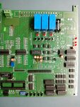
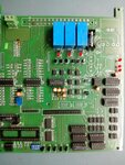
I have used SMPS of 12V.
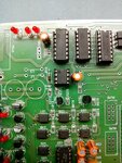
 trigger is not the problem......... it is some where else