Continue to Site

Welcome to EDAboard.com

Welcome to our site! EDAboard.com is an international Electronics Discussion Forum focused on EDA software, circuits, schematics, books, theory, papers, asic, pld, 8051, DSP, Network, RF, Analog Design, PCB, Service Manuals... and a whole lot more! To participate you need to register. Registration is free. Click here to register now.

Multi-nRF24L01+ Pic Project

Status
Not open for further replies.

xbased

Member level 1
Joined
Apr 4, 2013
Messages
38
Helped
5
Reputation
10
Reaction score
5
Trophy points
1,288
Location
Greece
Activity points
1,492
Hello.

I have to make a project, something like "who pressed the button 1st" game.
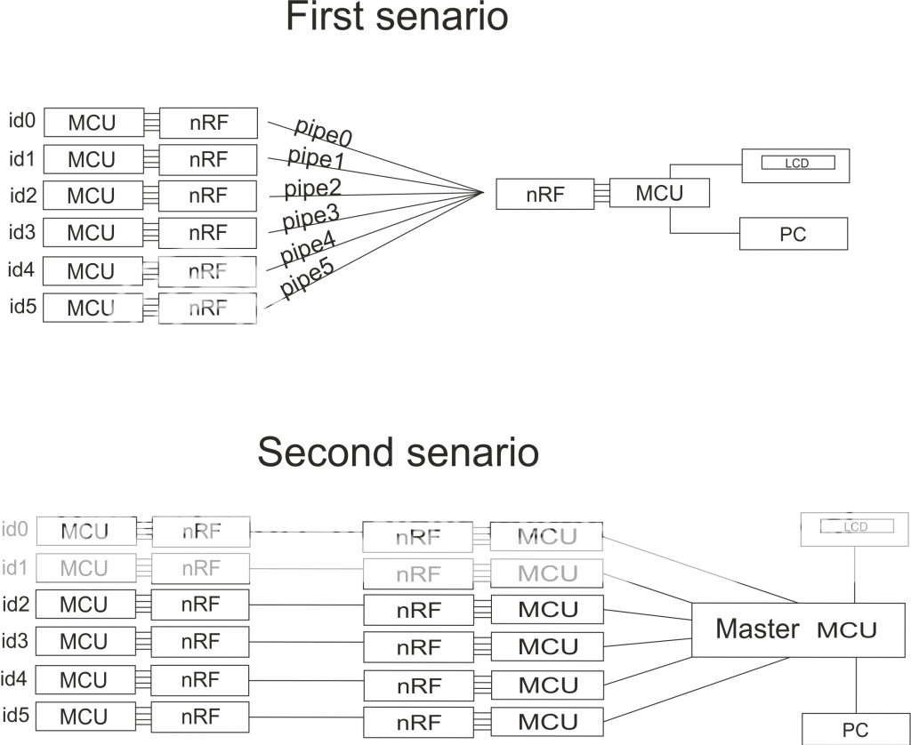
My idea is to use 6 nRF24L01+ with 6 MCU as TX units on the same freq using the 6 pipes available, and 1 more nRF24L01+ and MCU as RX. I just need each TX to transmit its own ID (1 byte maybe like A,B,C,D,E,F, not sure) to the RX MCU. The RX MCU then has to decide the order the TX ID's received (B,C,A,F,D,E lets say), and get the results on an lcd attached on RX MCU, or pass them to a pc via 232. I want to use PIC's as MCU's because i already have a PIC programmer. Also these nRF24L01+ boards come handy in price:

**broken link removed**

Also i have read some tutorials in this site: http://www.diyembedded.com/tutorials/nrf24l01_0/nrf24l01_tutorial_0.pdf.

Here i have some questions as i am not an expert in PIC or C and i only know how to use MikroC.

0. Is my idea able to work with these parts, or i am totally in the wrong way?
1. What type of pic you suggest i use, in order to make it work. I know i can use any SPI capable MCU but what is easier and handy without having to create hundreds of lines of code? (also i have already a few 16F628A and some 16F877A laying around).
2. Is it possible the RX nRF24L01+ and the RX MCU been able to monitor 6 TX ID's coming almost the same time?
3. Can i supply 3v power to the nRF24L01+ from MCU's PWM output?
4. Is there any way kind of code or schematic online so i can start with?

These are my thoughts so far.
Thanks for your time to read all these.
 

Will you have nRF24l01 connected to 6 Tx MCUs and 6 Rx MCUs (12 in total)? nRF24L01 used SPI Communication and if your i6F628A and 16F877A has SPI support then you can use the hardware SPI otherwise you have to use Software SPI.

Can you explain in detail how your "who pressed first" works? Why do you need to have 6 Tx? Can't you have 1 Tx MCU and 1 nrF at the Tx MCU and 6 buttons for 6 users. Only the first button press will be registered and a corresponding code will be sent through nRF at the Tx MCU side to the nRF at the Rx MCU side.
 
  • Like
Reactions: xbased

    xbased

    Points: 2
    Helpful Answer Positive Rating
The project is as follow:
6 people have 6 transmitting units in their hands. A question is made and all six press their button. I want to know the order their buttons were pressed so they can answer in that order.
It is handy if each one of the 6 have their own transmitter, without cables etc.
My thought is 6 transmitters using the same freq but different pipe, and 1 receiver that receives data to all 6 pipes at that freq.
 

You should have 6 Tx Units each with a MCU and one Rx Unit with MCU which supports HW SPI. If there is no HW SPI then you have to use Software SPI. What if more than one person press the button at the same time and what if data from all the transmitters come to the receiver at the same time? What will the receiver do? How will the receiver then decide who pressed first?
 
  • Like
Reactions: xbased

    xbased

    Points: 2
    Helpful Answer Positive Rating
Thats my point!
Will the reciever be able to handle 6 data at the same time at the 6 pipes?
According to nRF24L01+ datasheet at section 7.7 it IS possible.

Multiceiver is a feature used in RX mode that contains a set of 6 parallel data pipes with unique addresses.
A data pipe is a logical channel in the physical RF channel. Each data pipe has its own physical address
decoding in the nRF24L01.

nRF24L01 configured as PRX (primary receiver) can receive data addressed to six different data pipes in
one frequency channel as shown in Figure 10. Each data pipe has its own unique address and can be configured
for individual behavior.
Up to six nRF24L01s configured as PTX can communicate with one nRF24L01 configured as PRX. All
data pipe addresses are searched for simultaneously. Only one data pipe can receive a packet at a time.
All data pipes can perform Enhanced ShockBurst™ functionality.
The following settings are common to all data pipes:
• CRC enabled/disabled (CRC always enabled when Enhanced ShockBurst™ is enabled)
• CRC encoding scheme
• RX address width
• Frequency channel
• Air data rate
• LNA gain
The data pipes are enabled with the bits in the EN_RXADDR register. By default only data pipe 0 and 1 are
enabled.
Each data pipe address is configured in the RX_ADDR_PX registers.

Each pipe can have up to 5 byte configurable address. Data pipe 0 has a unique 5 byte address. Data
pipes 1-5 share the 4 most significant address bytes. The LSByte must be unique for all 6 pipes.

The PRX, using multiceiver and Enhanced ShockBurst™, receives packets from more than one PTX. To
ensure that the ACK packet from the PRX is transmitted to the correct PTX, the PRX takes the data pipe
address where it received the packet and uses it as the TX address when transmitting the ACK packet.
Figure 12. is an example of how address configuration could be for the PRX and PTX. On the PRX the
RX_ADDR_Pn, defined as the pipe address, must be unique. On the PTX the TX_ADDR must be the same
as the RX_ADDR_P0 and as the pipe address for the designated pipe.

No other data pipe can receive data until a complete packet is received by a data pipe that has detected its
address. When multiple PTXs are transmitting to a PRX, the ARD can be used to skew the auto retransmission
so that they only block each other once.
 

Then you can use it. Each nRF at Tx will have its own address and the first to transmit will be received by nRF at Rx.

What about the remaining 5? Thats the point.
According to the datasheet, it takes only a few mS for the data transmission. After the 1st reception at a pipe, will the following 5 data be received too?

A second thought was to use a pair of TX-RX nrf-mcu for each user, then get the 6 RX results to a seperate PIC, which will handle the order etc. What you think?
 

There is a option for re-transmission. Are you telling that there will be one Tx and one Rx for each user and the 6 Rx will be connected to one PIC? The problem is nRF cannot accept data when it is reading another data.
 

There is a option for re-transmission.

So, if the RX nrf is currently receiving a data and another data is coming, the first data will be accepted, and the second will be retransmited, so in result, the RX nrf will recieve the 2 data eventually, am i correct?
 

Yes. If re-transmission is used. I think when nRF is receiving data from one Tx and another data comes from another Tx then nRF will detect it because nRF at the Rx has to request for re-transmission. Post the datasheet of nRF.
 
  • Like
Reactions: xbased

    xbased

    Points: 2
    Helpful Answer Positive Rating
Post the datasheet of nRF.

Here it is. nRF24L01+ datasheet.

- - - Updated - - -

Here is a quick sketchup of the two senarios

nrf.png
 

Well in the 2nd senario what happens if all the 6 nRF's at the Rx side receive data from the Tx of the first person who pressed the button? It is the same thing as the first senario. all nRF at the Rx side receives the data of 1st user at the same time and then data of other users are re-requested. Is there any what to make each nRF at the Rx side to pick only data from one user? If, yes, it is better.
 
  • Like
Reactions: xbased

    xbased

    Points: 2
    Helpful Answer Positive Rating
Well in the 2nd senario what happens if all the 6 nRF's at the Rx side receive data from the Tx of the first person who pressed the button? It is the same thing as the first senario. all nRF at the Rx side receives the data of 1st user at the same time and then data of other users are re-requested. Is there any what to make each nRF at the Rx side to pick only data from one user? If, yes, it is better.

I think second scenario is possible because you can specify the freq that nrf TX and RX will work. So you just have to specify 6 different freqs for the 6 pairs and the problem is solved. Right?
 

Yes. Is there any way to make each nRF at Rx to receive data from one nRF at Tx ie., nRF at Tx sends some address and if nRF at Rx can be made to receive data only from set address?
 

Yes according to datasheet.

The RX address for data pipe 0 (RX_ADDR_P0) has to be equal to the TX address (TX_ADDR) in the PTX device. For the example in Figure 12. on page 37 the following address settings have to be performed for the TX5 device and the RX device:
TX5 device: TX_ADDR = 0xB3B4B5B605
TX5 device: RX_ADDR_P0 = 0xB3B4B5B605
RX device: RX_ADDR_P5 = 0xB3B4B5B605
 

Ha, have 10 of these on the way myself, for more normal transmitting but still funny..


Recognize collisions etc will make it where you can't really use the RF to tell who actually pressed the button first. Say 1 and 2 collide, then 3 presses and gets through, 3 looks like the winner when really they were well behind. Realistically the transmission may be fast enough that collisions don't happen enough to bother fixing it though.

You could have the main controller send out a heartbeat, and the button controllers sync to it and keep their own internal timing. Then on button press report their timing, that way it doesn't matter which transmission gets through first, it's the lowest timing button press that was first.

If you're not already familiar, stagger the retry timing for sending from each button unit.

1___1
2______2
3_________3

Etc, that way even if there is a collision or two they'll all eventually get their button timing sent through..
 
Thanks for the ideas so far!

Ha, have 10 of these on the way myself, for more normal transmitting but still funny..

Same here :wink:

You could have the main controller send out a heartbeat, and the button controllers sync to it and keep their own internal timing. Then on button press report their timing, that way it doesn't matter which transmission gets through first, it's the lowest timing button press that was first.

I am looking for some sample code of nrf communication in MicroC. It does not have to be written for my project, just to overview the whole TX-RX procedure. Any suggestions/links?
 

Google usually works..

http://www.mikroe.com/forum/viewtopic.php?f=88&t=50939

http://blog.diyembedded.com/ on the right side..

http://maniacbug.wordpress.com/2011/11/02/getting-started-rf24/

http://en.wikipedia.org/wiki/Manchester_code

FSI000A
315MHZ, 433MHZ

A315, A434

nRF24L01

Plug it in without the plus on google since that's a minor change. Even if you have no interest in Arduino, you should get a couple of the atmega328 nano versions for $10 each, just to have on hand and run the examples code. Since they are relatively easy there tends to be a ton of sample code made for the Arduinos. Easy to see what's going on in the example code even if you don't really use the Arduino.

Fsi000a and the a315 a434 are simpler but similar modules, haven't checked everything but the nRF is probably just doing the same, except on 2.4ghz. Best if there aren't long strings of 0s or 1s, since AGC etc won't like it. Look up Manchester encoding too.

On that maniacbug note reading through the comments and people's problems and solutions is as informing as the post..

Even if you use someone's library to run them, it's better if you have some idea of what's going on underneath. And better to look at the cheap 315 and 433 mhz modules on ebay too while you're at it. They make it through walls and around obstacles better, and typically greater distance, so likely to come in handy for something else later on, but most are only one way, you'd take 2 sets to go back and forth.

Anyway tons out there, shouldn't take an afternoon or two to get up on it after you get the modules..
 
  • Like
Reactions: xbased

    xbased

    Points: 2
    Helpful Answer Positive Rating
Thanks for the replies so far. In a few days i get the nRF's in my hands, gonna test them and come back again :)
 

Have gotten mine in, and been looking around a little more. They are a lot more sophisticated than the other simple transmitters, so more to do setup but less to program after that..

Several things..
You had the pipes in your first post. You probably don't really have to have them transmit ID's though, pipe 0 probably goes in one location, pipe 1 in another, etc so the controller will know simply by polling and where it gets 'buttonpress'. Just send a 'B' or something is probably enough.
And from page 39 on the datasheet:
"Only when a data pipe receives a complete packet can other data pipes begin to receive data. When multiple
PTXs are transmitting to a PRX, the ARD can be used to skew the auto retransmission so that they
only block each other once."

So they can be set up to auto skew, and the module already seems to handle retransmissions until it gets an ACK or similar if you sent them up for acknowledgement. So while you have to figure out more to get it set up correctly, after you do that in your program, there seems like little to do but wait for a button press and send a 'B' from the button controllers. Base doesn't do much besides clear the pipes right after the question is asked, then scan for which pipe has the first 'B'. Not much to it. The data rate is so fast you're really unlikely to have collision events for just sending a fast 'B' packet, so a collision and then out of order packet arrival will be so unlikely it isn't even worth programming for it.

If that MicroC example wasn't enough, download the arduino environment so you can see code examples, then get the RF24 library and examples here:
**broken link removed**

Some more stuff here, different simpler library..
**broken link removed**

Not sure those fully implement the pipes system, but once you have the modules running and some set up code working, it shouldn't be much more to use the data sheet and get pipes working.

The modules need a 3.3V supply. Pretty sure the inputs are 5V tolerant but double check in the datasheet.

Also take a look at these items, then a little more after:

**broken link removed**

**broken link removed**

**broken link removed**


6 of the boards would be $30, and get 2 of the adapters for programming and backup. Really once you have headers on the board and FT232 adapter, you can just plug them into the same pins on an IDE cable etc to hook them up for programming, so the cable wouldn't be 100% necessary.

Arduino used to make no sense, when everything was $25 a board. At $5 for a board, they are probably cheaper than doing this with the raw PICs by the time you get all the parts, and wire it up. You just put headers on, plug it together, and download over USB. Get a few extra boards, you only need one FT232 and a spare, then get M-M, M-F, F-F cables, some breadboards etc, and you can develop small projects like this much easier since the processors are already wired up and running. NANO 328 versions are a little more convenient since the USB 232 adapter is built in, but $9-10 each it adds up if your project doesn't really need the USB.

I was never an Arduino fan before and just started running into the cheap modules looking for parts, and at $5 a module they simply make a lot of sense now vs building up your own controller for a 5 or 10 off, one time project. If you have need or enjoy doing projects like this, it will benefit you in the long run to get a few running, just because it's so easy and there's so much easy to use already done example code.

Later
 
  • Like
Reactions: xbased

    xbased

    Points: 2
    Helpful Answer Positive Rating
Status
Not open for further replies.

Similar threads

Part and Inventory Search

Welcome to EDABoard.com

Sponsor

Back
Top