Continue to Site

Welcome to EDAboard.com

Welcome to our site! EDAboard.com is an international Electronics Discussion Forum focused on EDA software, circuits, schematics, books, theory, papers, asic, pld, 8051, DSP, Network, RF, Analog Design, PCB, Service Manuals... and a whole lot more! To participate you need to register. Registration is free. Click here to register now.

Question about a 5 to 32 decoder

Status
Not open for further replies.

goldsmith

Advanced Member level 6
Joined
Dec 14, 2010
Messages
3,981
Helped
741
Reputation
1,486
Reaction score
726
Trophy points
1,413
Location
Tehran - IRAN
Activity points
24,546
Dear All
Hi
Thank you for your attention and time .
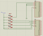
Some days ago a friend of mine asked me for making a 5 to 32 decoder using two 4 to 16 decoders . and as i've understood he is in hurry . but i'm an analog designer and i can't do it because my experience in digital is so limited .
In fact i'm looking for it's circuit which has been simulated via proteus . i want help my friend but i can't because i don't know how to do it .
I'll be grateful if someone can help me and my friend .
Thanks in advance
Goldsmith
 
Last edited:

Use the the first 4/16 decoder to decode the first 4 bits, and use the first input from the second 4/16 decoder to decode the 5th bit of the input. Two 4/16 decoders when used in full can decode an output number up to 255 but if you ground the higher 3 inputs of the second decoder only a number up to 31 will be outputed. Some outputs of the second decoder will always output logic 0 as the input combination needed to high them (logic 1) can't be reached (you would need to use the remaining 3 inputs of the second decoder).
 
Last edited:
Use the the first 4/16 decoder to decode the first 4 bits, and use the first input from the second 4/16 decoder to decode the 5th bit of the input. Two 4/16 decoders when used in full can decode an output number up to 255 but if you ground the higher 3 inputs of the second decoder only a number up to 31 will be outputed. Some outputs of the second decoder will always output logic 0 as the input combination needed to high them (logic 1) can't be reached (you would need to use the remaining 3 inputs of the second decoder).
Hi dear T3STY
Thank you very much for your prompt reply and of course helpful reply .
As i've mentioned before i'm looking for it's simulated file with proteus . can you please send me it's simulated circuit ? ( in proteus ) thus i can send it to my friend .
Thanks once again
Goldsmith
 
Last edited:

Yes, here's a design I just made. Unfortunately, my switch libraries decided not to work properly so for me changing the switch state won't change the switch output, so nothing changes on the decoders too. But it should work fine for you.

EDIT
I just noticed I used 4/10 decoders instead of 4/16. Well, nothing changes a part the fact that 4/16 decoders have 16 output lines instead of 10, input connections remain the same.

ReEDIT
Posted a correct version ;)
 

Attachments

  • 5_32__4_416__corrected.zip
    74.9 KB · Views: 87
  • 5_32--4_16__corrected.png
    5_32--4_16__corrected.png
    13.3 KB · Views: 253
Last edited:
Yes, here's a design I just made. Unfortunately, my switch libraries decided not to work properly so for me changing the switch state won't change the switch output, so nothing changes on the decoders too. But it should work fine for you.

Wow ! thanks for the suitable design really . i really appreciate you .
But when i run the circuit keys are not working . what can be the problem ? can you please tell me what is the problem of those keys ? a strange thing is when i've shorted keys , the status didn't change . perhaps those ICs are not active ? ( perhaps they don't have ability of simulation . as i can remember some of the ICs were like this )
Can you please help me to find the problem ?
Thanks in advance
Goldsmith
 

Acutally.. I have no idea. In my ISIS when I press the switches they won't change value, and actually they only stay high as long as they're attached to +5V.
The packages probably are broken... or probably, as you said, they're static packages which won't change values. I just tried some combinations of input but I always get all 0 or all 1 outputs... I suspect those packages are meant to work differently, but I'm not sure how.
If you consider the connections only though they're correct. You can tell your friend they're connected like that and if he studied just a bit about decoders he will confirm that they work. I suppose he'll make some laboratory experiments with real components, in this case he'll be able to proof they work on paper and in reality too :)
Thank you again for your effort . but as i know my friend wants it for his university as a project for his lesson . and it should be worked in simulation , unless his professor won't accept it .
I'll be grateful if you or someone else can help to solve this problem . that is so pity if i can't help my friend because he has helped me many times .
Thanks again
Goldsmith
 

Hi again . at last i could design it but myself however i'm not interested in such circuits !! ( me + help of digital designer of my group ! )

Anywhere , i've decided to share it here with peoples that are interested in such circuits . and about why proteus couldn't simulate something like that , the fault was : every digital circuit requires , a pull down or pull up resistor when input is float ! ( however for a moment of time )

By the way T3STY , your circuit had some problems ! you've grounded some of the inputs and it was absolutely wrong . however thank you for our effort .

Ok here that circuit comes :

5to32 decoder.JPG


Best Wishes for all
Goldsmith
 

Attachments

  • 5to32.rar
    12.2 KB · Views: 85

Actually, I can't understand the logic behind your circuit... by using a switch and a NOT gate you're enabling one decoder or another, but whichever is activated, will display the same number.
However, if it's what you needed then I'm glad you made it :)
 

Actually, I can't understand the logic behind your circuit... by using a switch and a NOT gate you're enabling one decoder or another, but whichever is activated, will display the same number.
However, if it's what you needed then I'm glad you made it :)
Hi My friend
Let me explain what that circuit will do :
When we set enable of each decoder in high state it will work and when we set it in low state t won't affect any changes in inputs .
So if we use a not gate it will play role of activator for us . ( latest bit ) it will disable the first decoder while latest bit is enabled .
So thus decoders can shift a bit as well . ( when 1st one is off second one is on and while second one is off first on is on ( on means enable =1 ) .
And also , the resistors has been added to make a logical state for each input . to avoid from floating ( high - Z state ) .

Is that clear now ?

But i'm thankful to you because you've made effort for me , that night . hence i need to appreciate you and your effort again .
best Regards
Goldsmith
 

Status
Not open for further replies.

Similar threads

Part and Inventory Search

Welcome to EDABoard.com

Sponsor

Back
Top