ALERTLINKS
Advanced Member level 4
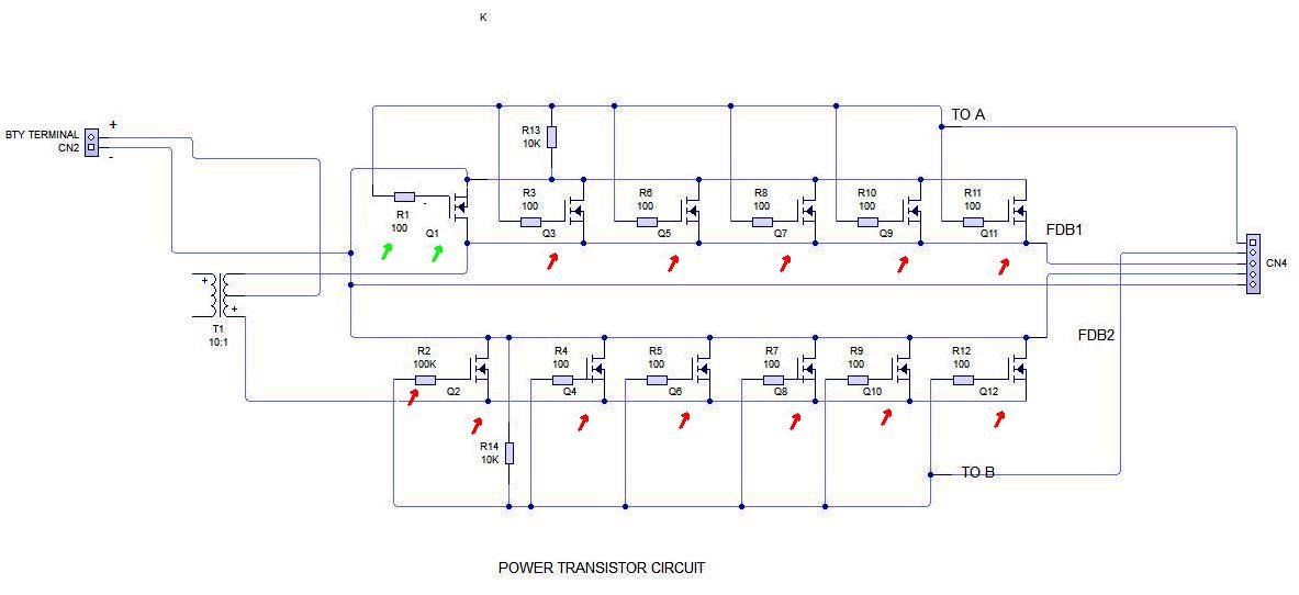
All FETs are shown connected wrong way. This must only be in schematic drawn otherwise inverter won't be working. Similarly R1 And R2 be 100 ohm like other gate resistors.

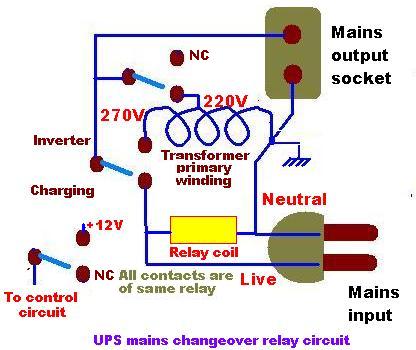
When mains is restored, a relay connects mains input to mains output after disconnecting inverter output and also disconnects DC from control circuit.
Last edited: