Continue to Site
Follow along with the video below to see how to install our site as a web app on your home screen.
Note: This feature may not be available in some browsers.
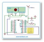
i want to make remote control led On/off circuit using 433Mhz RF transmitter and receiver
how can i do that
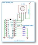
if you still want to use micro controller then you can replace HT-12E & Ht-12D from Rx & Tx side with Controller
i feel hard to understand this
HT-12E and HT-12D has only 4 data input and output pins is there any other chip has more than that?
i think you mentioned about RC IC
But i mentioned about
this is my one
View attachment 80912
receiver has only 4 pins
but lots of circuit diagrams based on 8 pin receivers
For testing on table no antenna is required.
how they transmit signals without antenna?