Continue to Site

Welcome to EDAboard.com

Welcome to our site! EDAboard.com is an international Electronics Discussion Forum focused on EDA software, circuits, schematics, books, theory, papers, asic, pld, 8051, DSP, Network, RF, Analog Design, PCB, Service Manuals... and a whole lot more! To participate you need to register. Registration is free. Click here to register now.

Ideas to obtain 12VDc from 400VAc

Status
Not open for further replies.

factory37

Newbie level 5
Joined
Sep 9, 2012
Messages
10
Helped
0
Reputation
0
Reaction score
0
Trophy points
1,281
Activity points
1,378
Hi everyone!
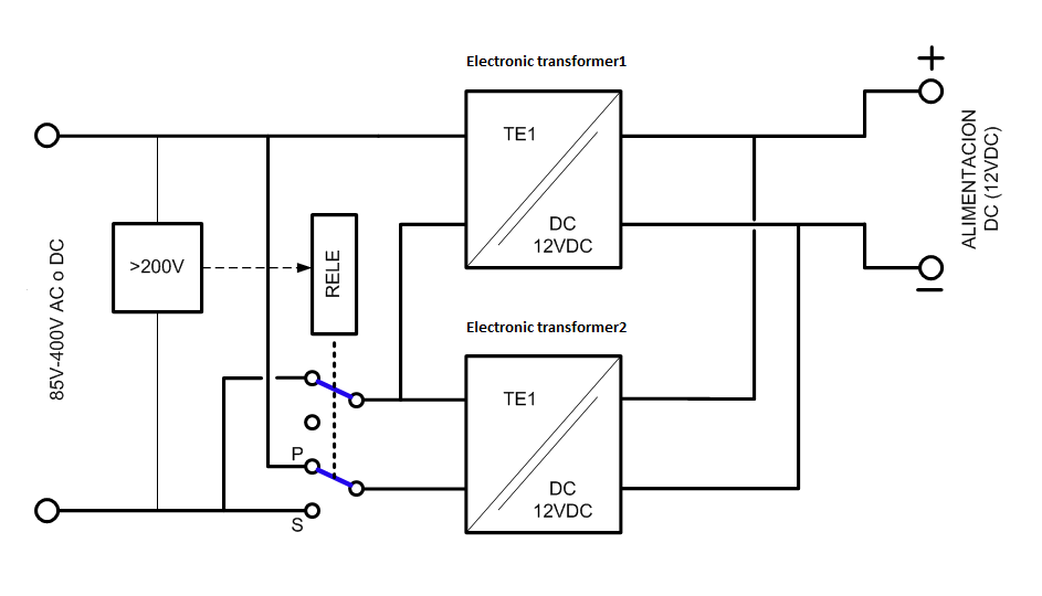
I want to desing a power supply to obtain an output of 12V from an input in the range of 85V-400V AC or DC.It has to supply 3W. I've thought to use electronic transformers, (myrra 47134) that some of its advantages are high performance, wide range of input voltages and operating indistinct both AC and DC. They accept an input of 85-265VAC y 85-370VDC, so I think a topology like this to achieve 400V input.
For low voltages, the input sections of the two transformers are connected in parallel. A relay is activated when the input voltage exceeds 200V so that both transformers will be connected in series.


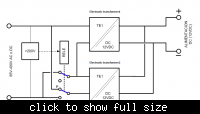
These transformers are based on flayback topology so I begin to think that when they work in series the gorund of the high transformer will be floating so it will turn crazy and I begin to think that it won't be able to work
Someone has some idea to transfor this input? are there any comercial product which can help me?
Thanks
 

Attachments

  • Myrra 47134.pdf
    158.5 KB · Views: 88

Will this product be mass produced or a single piece would be made?

I would suggest you to use capacitor drop with multistage filter. as a simple solution.

If you are not going to mass produce this you can use mobile charger that produce 5V/ 0.8A and use simple boost regulator at its output to get 12V.

If I get your exact requirement and your need, we would be able to guide with real life circuit.
 

Thank you both
I've been thinking about the design all day and I think I should focus more on solving the problem as genovator says.
As for the specific application it's for use in industry and it will be part of a sensing system. It Will be a series of five prototypes and if the result is satisfactory, proceed to do 100 more.
I don't understand what you mean by drop with multistage filter capacitor ...
I worry what will be the size of the flyback stage
Thanks

Sergio
 

Well Mr Factory it’s always very important where the product is going to be used. (Like industry, home appliances or something else.)

I had recommended using capacitor drop for home application. As it’s cheap and easy. (It needs some protection against surge) we will not discuss it here now as it’s not going to be implemented.

Next suggestion was using mobile charger as a supply. This was suggested keeping in mind that you might want this for single board. Also getting switching regulator for boost applications take only few handy components. (Wanted to keep you away from calculations of flyback making it easy)

Now when you have decided to go for flyback and you are looking for flyback of 3W, then in that case I would again say look at mobile charger. It’s the size you should end up with.

Flyback if designed poorly will not last for long. So be careful. Especially perfectly calculating snubbers and selection of mosfet plays a very important role. Also the secondary side diodes.

What is the ripple voltage expected at output at full load?
 
Finally today I tried to put the Myrra 47134 in series to handle this increased tension and they work properly. So I think I will continue with this idea, proving that it doesn't heat when it works for so long.
thanks you very much.:grin:
 

Not that I'm an expert in SMPS (I'm not), but personally I wouldn't do this. Firstly, you're assuming that the two series devices will ensure no more than 265V across one of the devices, and secondly you've got the input supply across the NO and NC terminals of the relay - something personally I'd be wary about (maybe I'm overworrying) but finally what if one of the contacts is a little slower in switching from parallel to series? Then, the top device gets the full supply across it.
 

you need a purpose built switch-mode converter to achieve this, 400AC is 565VDC nominal when rectified, usually a 2 switch flyback is employed for this, we have done several...
 
you need a purpose built switch-mode converter to achieve this, 400AC is 565VDC nominal when rectified, usually a 2 switch flyback is employed for this, we have done several...

I have never done this, although I read about it.

Pls correct me if i am wrong.

1) the design of transformer doesn't change it should be calculated like as for single switch.
2) this wont need snubbers, eliminating big losses @ snubbers.
3) efficiency can be lot better than single switch.
4) the energy due to leakage inductance is put back to power supply rails.
5) The vds of the mosfet selected for this purpose can be vin + 20%. wont need to cater with the reflected voltage.
 

Just a suggestion: Since output power is low, input peak current shouldn't be too high. So, you can try with a single switch flyback, using a 900V MOSFET, ensuring that the snubber you design keeps the peak drain voltage of the MOSFET to a sufficiently low level.
 

Status
Not open for further replies.

Similar threads

Part and Inventory Search

Welcome to EDABoard.com

Sponsor

Back
Top