Continue to Site

Welcome to EDAboard.com

Welcome to our site! EDAboard.com is an international Electronics Discussion Forum focused on EDA software, circuits, schematics, books, theory, papers, asic, pld, 8051, DSP, Network, RF, Analog Design, PCB, Service Manuals... and a whole lot more! To participate you need to register. Registration is free. Click here to register now.

[SOLVED] Mixer output has (LO+(IF/2)) components

Status
Not open for further replies.

shashy.br

Full Member level 2
Joined
Sep 15, 2011
Messages
130
Helped
6
Reputation
12
Reaction score
6
Trophy points
1,298
Location
India
Activity points
2,151
Hi all,

Thanq for supporting me in all my queries.

i have designed and fabricated a upper c band local oscillator with frequency ranges from 7.38 to 8.18 GHz,

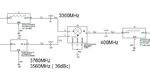
i am using a mixer to obtain the half of the required signal i.e( if 7380MHz is required i generate 3690MHz) and mulitply it finally to get the C band frequency spot.

the mixer utilized is ADE-42MH+ from Mini circuits ,while testing i found that the LO+(IF/2) is also available at the output.

I didn't know the mixers generate the IF/2+LO frequencies at the output,is this normal operation of a mixer?

Kindly let me know why this output is occurring and how to remove it.
 

How are you feeding the mixer? Are you splitting your 3690 MHz output into two, then one into the RF input and one into the LO input of the mixer, taking the output from the IF ? I can't understand what you are doing. It you are doing what I think you are doing, then the IF will be twice the LO. You need to explain your setup a bit better.
 
you mean you are seeing 5535 MHz? Your microwave source at 3690 must have some 0.5F content in it.

It is theoretically possible for a schottky diode to parametrically oscillate at 1/2 the input frequency, but VERY unlikely. I would look outside of the mixer for the source.
 
Thanq for the replies,

Please consider the following scenario

LO to the Mixer = 3360MHz (10dBm)
IF to the mixer = 400MHz (-4 dBm)

The RF output which is expected is 3760MHz, but i am getting a component at 3560MHz (36dBc w.r.t 3760MHz),


The signal 3560MHz is a combination of (LO+(IF/2)),

please let me know if any other information is required.
 

Attachments

  • Untitled.jpg
    Untitled.jpg
    34.4 KB · Views: 112

when you change the if to 300MHz, do you still see 3360+300 out and 3360+150 at 36dBc?
 
The case is the same when i change the IF from 250 to 660MHZ and maintain the LO at 3360MHz,
i have tested all the IF cases and found the LO+(IF/2) component existing in all the test cases.
 

check the IF source, do you observe f0/2 at the output of the IF source, ie 200MHz when IF source is at 400MHz?
 
Thanks for the replies,

I am not using the mixer to double the frequency ,
I have attached the diagram of my frequency generation scheme,
kindly let me know your suggestions.MEHTOD.jpg
 

check the if source, if u r still observing 2f0 there, you have to live with that. you can build variable filers for each signal but that will be tiresome.
alternatively you can use plls for 7-8ghz rfout which will solve your harmonic problem.
 
So you are effectively letting LO, LO+IF, LO-IF, + a bunch of NxM mixer products into your X2 doubler? Not so great a system design! The X2 multiplier, by its nature, will have a poor IP3 and all those products will cause 3rd order products at its output.

Also, there is a huge 2IF x 1LO product out of the mixer since the IF covers more than one octave.

If you really need low spurious, you might need a tracking filter, or a switched filter bank, between the mixer and the X2. Or put the X2 in the LO line only, maybe another x2 with switched filters on the IF line before the signals get to the mixer.
 
Thanks for the replies,

i have utilized the switched filter banks at the output of the mixer ,
i apologize for the lesser detail in the block diagram mentioned,

i have split the pass band into 2 paths each of 200MHz bandwidth.
 

Thank you all for sharing your experience,

i have debugged the problem at hand, it seems that the LOW frequency components have been radiating to the X band region and then the inter modulated to form the undesired components. I have separated individual section with mechanical isolation strips , which helped me remove the spurious components completely.
 

Status
Not open for further replies.

Part and Inventory Search

Welcome to EDABoard.com

Sponsor

Back
Top