Continue to Site

Welcome to EDAboard.com

Welcome to our site! EDAboard.com is an international Electronics Discussion Forum focused on EDA software, circuits, schematics, books, theory, papers, asic, pld, 8051, DSP, Network, RF, Analog Design, PCB, Service Manuals... and a whole lot more! To participate you need to register. Registration is free. Click here to register now.

Is there any general formula for RC phase oscillator for any no of stages?

Status
Not open for further replies.

SherlockBenedict

Member level 4
Joined
Dec 26, 2011
Messages
77
Helped
0
Reputation
0
Reaction score
0
Trophy points
1,286
Activity points
1,870
Consider an RC phase shift oscillator. I have used op-amp in this case.

For three stages we have frequency of oscillations as

ω= 1/ (2πRC √6)

What is the formula for n-stage RC phase shift oscillator?

Thanks a lot...:-D
 

Dear SherlockBenedict
Hi
Why you don't calculate it ? how do you found that formula ? simply you can demonstrate it ! ( certainly for N section it will not be simply ! but it will be funny ! )
Best Wishes
Goldsmith
 

In your formula, n=3. I think, by inspection:

mimetex.cgi


Where, n=3,9,... each RC stage contributes 60 degrees of phase shift.

But you can work it out. The derivation is quite lengthy.

ω= 1/ (2πRC √6)

And to use this equation of yours, you need to drop the 2π... It should be

mimetex.cgi


or

mimetex.cgi


for

mimetex.cgi
 
Last edited:
http://www.elektroda.pl/cgi-bin/mimetex/mimetex.cgi?3$f_%7Bosc%7D%3D%5Cfrac%7B1%7D%7B2%7B%5Cpi%7DRC%5Csqrt%7B2n%7D%7D

Hi dear Baas Rietrot
Your formula seems pretty good . but how you have calculated sqrt(2n) ? can you show , please ?
Regards
Goldsmith
 

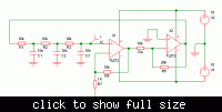
On a slightly unrelated note, you can get a low distortion sine wave oscillator by swapping the positions of the resistors and capacitors as in the circuit below.

The second pic shows the outputs of the two opamps. As expected the output of the 2'nd opamp is badly clipped because the loop gain is higher than needed, but the output of the first opamp is a good looking sine wave with less than 1% distortion.

The trick is that the phase shift network also acts as a low pass filter to remove most of the distortion. I'm surprized that the conventional arrangement is so popular and this variation is seldom, if ever, mentioned.

It can also be used with simple one transistor oscillators. In that case distortion isn't improved but biasing is easier, resulting in lower parts count.


Link from used in a previous discussion.

The previous edaboard discussion.

n May be many different values but the gain will change.

Hi Baas Rietrot, I am afraid that you have mentioned the link and its content without any proof by yourself.
As mentioned already by FvM (your second link) the formula with SQRT(2n) is false.
More than that, also the circuit as given in link#1 does obviously not work.

- - - Updated - - -

On a slightly unrelated note, you can get a low distortion sine wave oscillator by swapping the positions of the resistors and capacitors as in the circuit below.

Hey godfreyl,
yes, it is a circuit which works rather good - and probably you know that there are other oscillator topologies that exploits the filtering capabilities of the frequency determining network.
But one question: Why do you propose such a large gain ? (32 instead of 29.5 or 30)?

LvW
 
Last edited:
Why do you propose such a large gain ? (32 instead of 29.5 or 30)?
I don't recommend such a high gain. It was just to demonstrate the improvement, even with bad clipping.
 

Status
Not open for further replies.

Similar threads

Part and Inventory Search

Welcome to EDABoard.com

Sponsor

Back
Top