Continue to Site

Welcome to EDAboard.com

Welcome to our site! EDAboard.com is an international Electronics Discussion Forum focused on EDA software, circuits, schematics, books, theory, papers, asic, pld, 8051, DSP, Network, RF, Analog Design, PCB, Service Manuals... and a whole lot more! To participate you need to register. Registration is free. Click here to register now.

How to make a relay to work properly

Status
Not open for further replies.

myru28

Member level 1
Joined
Jun 22, 2012
Messages
33
Helped
2
Reputation
4
Reaction score
2
Trophy points
1,288
Activity points
1,558
I'm having trouble with making a relay to work and as the one I have doesn't have a datasheet I cannot work much on it

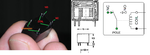
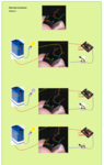
The relay is the one shown here: https://www.electan.com/product_thumb.php?img=images/P1010055.JPG&w=200&h=150 and I think that either 9V and (0 or 5V) should go to the pins that are left most, and depending on if I'm applying 0 or 5 Volts the pins at the right should be 9 for a value and 0 for the other, the other ping being exactly the opposite as the one at its side. Pins that are not seen and vertical to those ones should have the same value as that pin (I'll call the pin and the one it's vertical partners).

But in practice, I get 9 V for the right most pin and 0 for its partner and 0 for the others wether there's 0 or 5 V on entrance. So I guess I may be doing something wrong, and it's more worth asking than keeping on experimenting.

I also bought the relay sure that 5 V was the quantity needed to change the pin that gives the output on the delay, but maybe I was mistake, I also don't get a clue what those 55 Ω are about, if they have anything to do with the problem.

Thanks.
 

RN-CO 5_55
That's a 5V monostable miniature relay, for D.C. Equipped with a pole changeover capable of admitting resistive breakdowns of 1A.
Standard RN relays = 0.45 W, I =5V/55 ohms = 90 mA, so P = UI = 5V* 0.09A= 0.45W
See the attached diagram.

- - - Updated - - -

In the middle we have the two pairs of contacts = that’s the relay coil contacts. On the left side we have two pins, both connected to the movable contact. Near to the relay coil, on the right side we have the stationary contacts, one NC = 'normally closed', and the second NO = 'normally open'. With no voltage applied to the coil of the relay, the 'normally open' contacts are open. The 'normally closed' contact are connected to the movable contact. That NC connection would be broken with 5V voltage applied to the coil and make the normally open contacts closing the circuit to the movable contact
 

Attachments

  • RN_5-55.png
    RN_5-55.png
    210 KB · Views: 78

Thanks for your help, but I still don't get how I should connect it on my case, I'm showing the schematic of this part that I have to do to make things more clear, if anyone could tell me how the wires would be exactly connected to the relay I'd be very grateful:

80_1340971651.jpg


The point of the circuit is that when there's 0V between the collector of the transistor and GND a pin of the relay has to give 0 and when there's 5 V the same pin has to be able to move a motor connected to that pin (not shown on the schematic).

Thanks a ton.
 

Check the attached diagram... :grin:
 

Attachments

  • RN_5-55 connection.png
    RN_5-55 connection.png
    217.6 KB · Views: 82

    V

    Points: 2
    Helpful Answer Positive Rating
It still doesn't work... But I think it's more a problem of the relay being wrong than of the connection itself.

I mean, if the pin coil shown in the diagram is connected to the collector of transistor, even with a diode between them, voltage on the indicated pin is always 9 V, but if I ground it the relay does the sound that indicates it switches. I'd like to confirm this is indicating a malfunction of the relay, as I think what should be on that pin should be the 0 or 5 V from the collector.

Thanks a lot for your help.
 

First let’s do some simple tests without the transistor. Now need to check what are the correct pins arrangement for that relay.

Connect one pin of the relay coil to +5 V. The remaining coil pin to be connected to the GND time to time.

Use some light bulb and a power supply to match the necessary light bulb voltage.

See the diagram attached.
Verify which of the two situations may apply to that relay.
 

Attachments

  • RN_5 test 1.png
    RN_5 test 1.png
    1.1 MB · Views: 68
  • RN_5 test 2.png
    RN_5 test 2.png
    1.1 MB · Views: 75

Status
Not open for further replies.

Similar threads

Part and Inventory Search

Welcome to EDABoard.com

Sponsor

Back
Top