Continue to Site

Welcome to EDAboard.com

Welcome to our site! EDAboard.com is an international Electronics Discussion Forum focused on EDA software, circuits, schematics, books, theory, papers, asic, pld, 8051, DSP, Network, RF, Analog Design, PCB, Service Manuals... and a whole lot more! To participate you need to register. Registration is free. Click here to register now.

Help with a circuit question, please

Status
Not open for further replies.

LASERSC

Newbie level 4
Joined
May 24, 2012
Messages
7
Helped
0
Reputation
0
Reaction score
0
Trophy points
1,281
Activity points
1,328
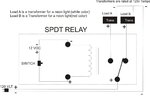
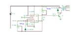
I am very new and only have limited knowledge. Any help would be greatly appreciated. The circuit attached below is what I think I need. The circuit will control flow to two transformers that are attached to two neon lights. When the switch is pressed it should move power to load A and back to load B when released. Eventually I would like to replace the switch with a timer, which would allow each lamp to stay on about 3-5 min before switching. My question is, is this a good circuit design. It is my first attempt at a drawing so it is nothing more than a rough sketch. Thanks for any input.

Richard
 

Attachments

  • SPDTRELAY..jpg
    SPDTRELAY..jpg
    92.2 KB · Views: 155

I think it’s the best solution to use a timer, the question is: do you want to make one timer (by using a standard 555 circuit, capacitors and resistors) or considering buying off the shelf product?

---------- Post added at 19:37 ---------- Previous post was at 19:30 ----------

e.g. Timedelay relays
https://www.serelays.com/library/section5/105A_820_Series.pdf
 
Circuit looks okay if you use ordinary switch to control the relay, for control using an external circuit (like based on 555 timer) it would need a diode across the relay coil to avoid a voltage spike going back into the control circuit.

If the lamp characteristics are similar enough, you could use 1 transformer, and use the relay to determine which lamp is connected across the transformer output.

Another option is to use a relay that only needs a jolt of power to switch position (but not continuously). Then you'd use a pulse of current to switch outputs, but don't need to power the relay continuously in 1 position.
 
I think it’s the best solution to use a timer, the question is: do you want to make one timer (by using a standard 555 circuit, capacitors and resistors) or considering buying off the shelf product?

---------- Post added at 19:37 ---------- Previous post was at 19:30 ----------

e.g. Timedelay relays
https://www.serelays.com/library/section5/105A_820_Series.pdf

I like the idea of off the shelf... but I also like to build. Do you think I will be able to find a relay that the coil would also
work on 120v so that I may only have one circuit. Also, do they have off the shelf times that will swing off and on every
3 to 5 min. well that is reasonable. This is just a fun do at home project.... Thank you for your reply and help

ps any 555 timer circuit diagram that would do what I need would be greatly appreciated.

Thanks I do appreciate all the replies!!!!
 

As for the 555 circuit we need using some separate 9-12V power supply, the relay coil may also be rated for 12V. See foe example a timer diagram attached.

More details about 555 circuit/timings here:

**broken link removed**
 

Attachments

  • Timer 555a.png
    Timer 555a.png
    57.8 KB · Views: 130
  • Timer 555.png
    Timer 555.png
    60.5 KB · Views: 124
  • Like
Reactions: LASERSC

    LASERSC

    Points: 2
    Helpful Answer Positive Rating
    V

    Points: 2
    Helpful Answer Positive Rating
Thanks mister_rf.... you ROCK! I do appreciate the reply, circuit layout and pic!

---------- Post added at 09:49 ---------- Previous post was at 09:00 ----------

mister_rf.... I have another question after looking more closely at the circuit.... Do you know what the value of T1 would be.
 

Use any NPN small bipolar transistor e.g.
BC171/BC173/BC547/BC548/BD135/BD137/BD139/2N2222/
 
once again...thank you so much... am off to build circuit.
 

First you need to find a suitable relay. To keep some safe room you need a minimum 12-15Amps relay 120Vac rated.
You may use a PCB mounted relays
e.g.

G2RL-1-DC12.jpg

Relay_BS-115C-12A-12V.jpg


or panel mount power relays
**broken link removed**
 
WOW, you are making it so easy for me, thanks... and again another question will 1/4 watt resistors work in this circuit?
 

Yes, no special resistors, usually the 1/4W will do the trick.
By the way, have you already decided for the exact timings? Based on the timings we can calculate capacitor/variable resistors values.
 
I am thinking maybe 5 min on then 5 min off... I don't want to be too harsh on the transformers.
I am thinking too many power cycles may not be a good thing. I don't think I would have the circuit on more
than a couple of hours at a time..

thanks mister_rf
 

For a long period of time you need to increase the variable resistor values up to 250k-470k and the capacitor value up to 1000uF-2200uF. But sometimes there’s a problem with long times and the leakage currents of the timing capacitor, PCB quality and the type of 555 used for. It is usually best for longer times to use the CMOS version of the 555 (TLC555CP).
https://www.ti.com/lit/ds/symlink/tlc555.pdf

Maybe it’s better to run a counter (e.g. CD4060).
Circuit looks also very simple.

https://www.coolcircuit.com/circuit/timer_4060/

Testing the CD4060 timer circuit:


Status
Not open for further replies.

Similar threads

Part and Inventory Search

Welcome to EDABoard.com

Sponsor

Back
Top