Continue to Site

Welcome to EDAboard.com

Welcome to our site! EDAboard.com is an international Electronics Discussion Forum focused on EDA software, circuits, schematics, books, theory, papers, asic, pld, 8051, DSP, Network, RF, Analog Design, PCB, Service Manuals... and a whole lot more! To participate you need to register. Registration is free. Click here to register now.

[SOLVED] Lcd 16x2 and atmega8 with codevision

Status
Not open for further replies.

#MAAM#

Full Member level 2
Joined
Nov 21, 2009
Messages
131
Helped
29
Reputation
58
Reaction score
27
Trophy points
1,308
Location
Egypt
Activity points
1,920
My greetings,

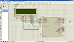
I tried to write hello word on lcd 16x2 with atmega8 and the word doesn't display. this is my code

Code:
/*********************************************
This program was produced by the
CodeWizardAVR V1.23.8c Professional
Automatic Program Generator
© Copyright 1998-2003 HP InfoTech s.r.l.
http://www.hpinfotech.ro
e-mail:office@hpinfotech.ro

Project : 
Version : 
Date    : 2012-05-21
Author  : Abbas                           
Company :                                 
Comments: 


Chip type           : ATmega8
Program type        : Application
Clock frequency     : 1,000000 MHz
Memory model        : Small
External SRAM size  : 0
Data Stack size     : 256
*********************************************/

#include <mega8.h>
  
// Alphanumeric LCD Module functions
#asm
   .equ __lcd_port=0x18
#endasm

#include <lcd.h>
// Standard Input/Output functions
#include <stdio.h>

// Declare your global variables here
char lcd_buffer[16];

void main(void)
{
// Declare your local variables here

// Input/Output Ports initialization
// Port B initialization
// Func0=Out Func1=Out Func2=Out Func3=Out Func4=Out Func5=Out Func6=Out Func7=Out 
// State0=0 State1=0 State2=0 State3=0 State4=0 State5=0 State6=0 State7=0 
PORTB=0x00;
DDRB=0xFF;

// Port C initialization
// Func0=In Func1=In Func2=In Func3=In Func4=In Func5=In Func6=In 
// State0=T State1=T State2=T State3=T State4=T State5=T State6=T 
PORTC=0x00;
DDRC=0x00;

// Port D initialization
// Func0=In Func1=In Func2=In Func3=In Func4=In Func5=In Func6=In Func7=In 
// State0=T State1=T State2=T State3=T State4=T State5=T State6=T State7=T 
PORTD=0x00;
DDRD=0x00;

// Timer/Counter 0 initialization
// Clock source: System Clock
// Clock value: Timer 0 Stopped
TCCR0=0x00;
TCNT0=0x00;

// Timer/Counter 1 initialization
// Clock source: System Clock
// Clock value: Timer 1 Stopped
// Mode: Normal top=FFFFh
// OC1A output: Discon.
// OC1B output: Discon.
// Noise Canceler: Off
// Input Capture on Falling Edge
TCCR1A=0x00;
TCCR1B=0x00;
TCNT1H=0x00;
TCNT1L=0x00;
OCR1AH=0x00;
OCR1AL=0x00;
OCR1BH=0x00;
OCR1BL=0x00;

// Timer/Counter 2 initialization
// Clock source: System Clock
// Clock value: Timer 2 Stopped
// Mode: Normal top=FFh
// OC2 output: Disconnected
ASSR=0x00;
TCCR2=0x00;
TCNT2=0x00;
OCR2=0x00;

// External Interrupt(s) initialization
// INT0: Off
// INT1: Off
GICR|=0x00;
MCUCR=0x00;

// Timer(s)/Counter(s) Interrupt(s) initialization
TIMSK=0x00;

// Analog Comparator initialization
// Analog Comparator: Off
// Analog Comparator Input Capture by Timer/Counter 1: Off
// Analog Comparator Output: Off
ACSR=0x80;
SFIOR=0x00;

// LCD module initialization
lcd_init(16);
lcd_clear();
while (1)
      {
      // Place your code here
	lcd_gotoxy(0,0);
	sprintf(lcd_buffer,"Hello");
	lcd_puts(lcd_buffer);
      };
}

i tried too much. the program is too simple but doesn't work. i upload also my schematic and simulation file with proteus and the source code. thanks in advance
 

Attachments

  • lcd_atmega8.JPG
    lcd_atmega8.JPG
    171.6 KB · Views: 249
  • proteus_lcd_16.rar
    5.4 KB · Views: 90
  • codevision_lcd.rar
    31.3 KB · Views: 88

1:Disconnect D0; D1; D2; D3 lines from GND. This lines have internal pull-up resistors.
2:Check defines of LCD lines.
3:Check pin3 on LCD module.(contrast pin) Pull it down to GND with a 10k pot.
 
Last edited:

1:Disconnect D0; D1; D2; D3 lines from GND. This lines have internal pull-up resistors.
2:Check defines of LCD lines.
3:Check pin3 on LCD module.(contrast pin) Pull it down to GND with a 10k pot.

1) the pins need to be connected to ground for 4bit operation
2) in codevision (up to v2) the pin definitions are standard, you only select the port
3) no need for that in the simulation, contrast is not modeled


The code works fine when compiled in v2.
Double check if the clock frequency setting is correct in the project properties.

Alex
 
  • Like
Reactions: #MAAM#

    #MAAM#

    Points: 2
    Helpful Answer Positive Rating
1) the pins need to be connected to ground for 4bit operation
2) in codevision (up to v2) the pin definitions are standard, you only select the port
3) no need for that in the simulation, contrast is not modeled


The code works fine when compiled in v2.
Double check if the clock frequency setting is correct in the project properties.

Alex

it still not working with me :(

are you had any other idea to help me
 

What other idea do you need?
Your code is fine , just download the new demo version and it will work fine

Another idea is to use your own LCD library **broken link removed**
and even change your toolchain to avrgcc
 

What other idea do you need?
Your code is fine , just download the new demo version and it will work fine

Another idea is to use your own LCD library **broken link removed**
and even change your toolchain to avrgcc

are you think avrgcc better than codevision ??
 

Better yes but more inconvenient to use,no more ready libraries, you either have to create your own or search the wed to make a collection you can use.
It will take some time to get used in working with the new environment and understand how to work.
gcc gives slightly smaller code and is faster when it comes to output switching... and its free.

The problem you have is related to bad timing, it is either the old library or the proteus model.
Have you tried a real hardware?
 

I use this 24x2 lcd module in my solar power controller and works fine in 4-bit mode with Atmega8. The controller works with all Hitachi compatibles without d0-d3 connected.
CIMG2328.JPG
CIMG2326.JPG
 
  • Like
Reactions: #MAAM#

    #MAAM#

    Points: 2
    Helpful Answer Positive Rating
1) the pins need to be connected to ground for 4bit operation
2) in codevision (up to v2) the pin definitions are standard, you only select the port
3) no need for that in the simulation, contrast is not modeled


The code works fine when compiled in v2.
Double check if the clock frequency setting is correct in the project properties.

Alex

the problem is solved by using version 2 of codevision. thanks for help alex. i upload image of working lcd.

alex.jpg
 

Status
Not open for further replies.

Similar threads

Part and Inventory Search

Welcome to EDABoard.com

Sponsor

Back
Top