baby_1
Advanced Member level 1
Hello
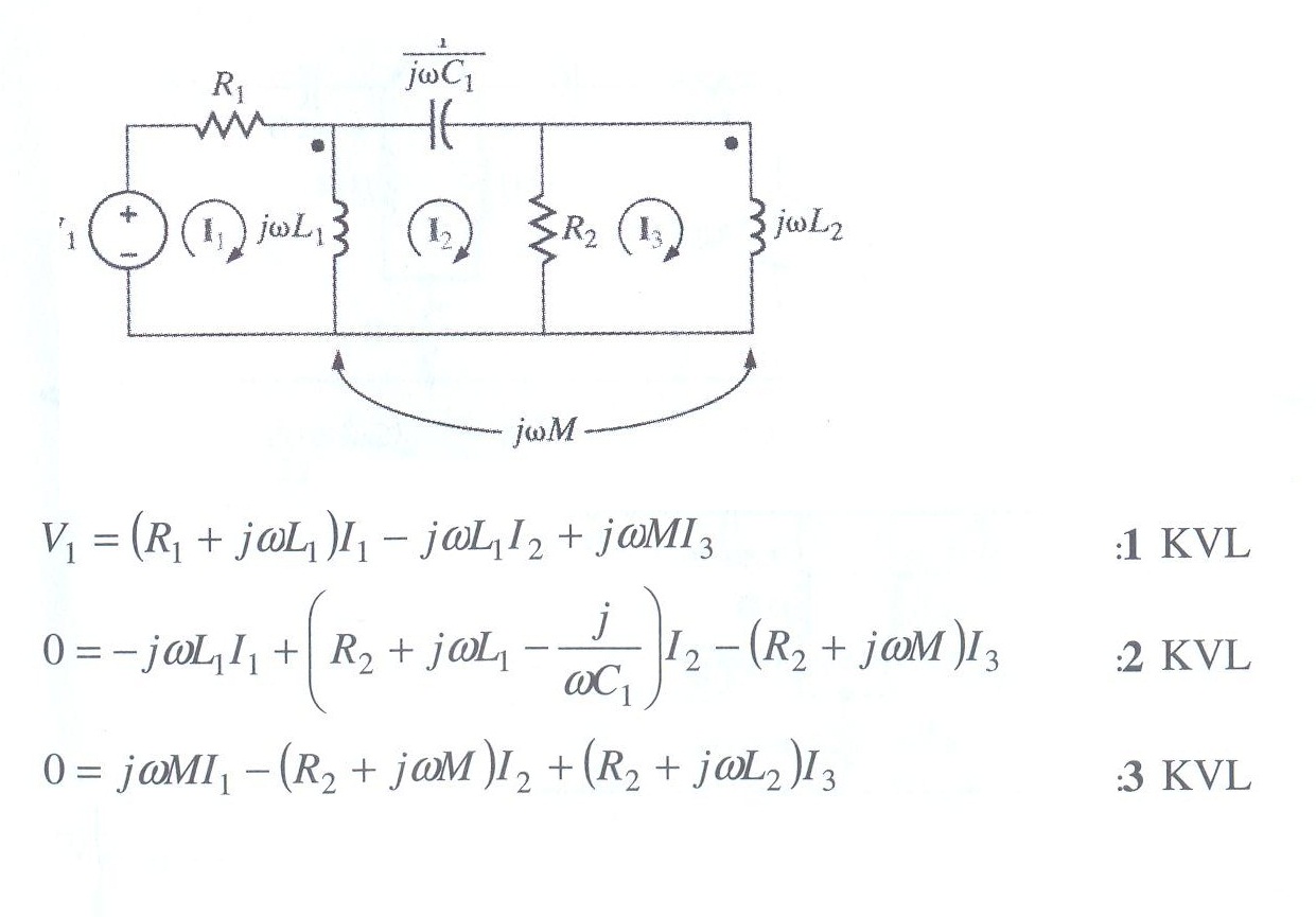
here is a problem that book writer solved it.i want to know why he put -mjwI3 in the equation 2 and we can't see it on other equation with negative sign?
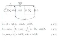
when we should put negative or positive sign for Coupled networks ?
here is a problem that book writer solved it.i want to know why he put -mjwI3 in the equation 2 and we can't see it on other equation with negative sign?
when we should put negative or positive sign for Coupled networks ?