Continue to Site

Welcome to EDAboard.com

Welcome to our site! EDAboard.com is an international Electronics Discussion Forum focused on EDA software, circuits, schematics, books, theory, papers, asic, pld, 8051, DSP, Network, RF, Analog Design, PCB, Service Manuals... and a whole lot more! To participate you need to register. Registration is free. Click here to register now.

Photo diode circuit not receiving signals continuously?

Status
Not open for further replies.

karthickb3e

Advanced Member level 4
Joined
Dec 13, 2010
Messages
101
Helped
3
Reputation
6
Reaction score
3
Trophy points
1,298
Location
INDIA
Activity points
1,883
Hi all,

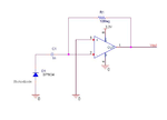
I assembled the photodiode op-amp circuit as shown in the below ......

Photodiode circiut.PNG

my emitted signal is 4khz.. The circuit not receives the emitted signal continuously..
i shown the my received signal in the following images...
Received signal1.JPG

Received signal2.JPG

Received signal3.JPG


there is some gap between the emitted signal... please help what is the problem how to solve this????
 

You have biased the opamp (non-inverting input) at zero volts and the most negative supply on the opamp is zero volts. So, the output cannot go below zero. I am not sure what you were expecting. Try biasing the opamp non-inverting input above zero volts.

Keith.
 

Maby yo try adding dc source on noninverting side input of 3.3v/2.
 

Another basic problem is operating the photo diode AC coupled - which restrict it to photo element mode, although zero biased current source would be much more sensitive. In addition, the AC current sourced to the amplifier will be half-wave rectified according to the chosen OP bias, as already explained. By removing the capacitor, the waveform should be shown completely, but with a DC bias according to the constant light intensity.

If you want to place an AC-coupling before the amplifier, the photo diode should have a DC bias as well.
 

thanks to all for the reply.....

1.) i try biasing to the non inverting terminal... it works ,,, but the pulse not as like the emitted pulse.... i need the exact pulse( zero to high) .. i change the C1 value to 100nF..to get exact pulse................... is it affect its response??? please clarify ...!


2.) and also which of the following configuration will work with high speed(response) and more efficient and less noise and why????
Fig 1:
Photodiode circiut.PNG

Fig 2:
Photo diode circuit 2.PNG

Fig 3:
Photo diode circuit 3.PNG
 

Attachments

  • Photodiode circiut.PNG
    Photodiode circiut.PNG
    50.7 KB · Views: 153
Last edited:

i think figure two is good enough.
because it has negative biasing.so it can conduct very fast and respond quickly.
but i dont know about the noise.
the noise may come..!!!!!!!!!!!!!
 

Unfortunately, all four schematics are ignoring the basic requirements of photo diode operation. They only differ by subsidiary details. :sad:

The circuits will give some response, but are slow and insensitive. Their AC gain will strongly depend on DC light level.

Please refer to the simple input stage circuit linked by dselec as a starting point or provide an equivalent DC path for the photo current.
 

i cant get it with the diagram , you said. i'm using AC signal. if i give that signal to the circuit you mention/ refer only DC output came. not AC output.
i need to place capacitor in front of the amplifier right....?
and also if i connect non inverting terminal to ground means , the output signal is not proper . as i shown in the first image...
what can i do for this...?
 

As previously said, the problem is with photo diode operation, not the amplifier.
 

thanks to all for the reply.....

1.) i try biasing to the non inverting terminal... it works ,,, but the pulse not as like the emitted pulse.... i need the exact pulse( zero to high) .. i change the C1 value to 100nF..to get exact pulse................... is it affect its response??? please clarify ...!


2.) and also which of the following configuration will work with high speed(response) and more efficient and less noise and why????
Fig 1:
View attachment 72061

Fig 2:
View attachment 72059

Fig 3:
View attachment 72060

Some cells need a bias and or parallel resistor to close the cell circuit so just add 10k resistor in series like the link shows and see what happens ,remember it is a light cell you need to let the electrons from the cell pass thru resistor and back to cell its really a dc cell that its dc value changes as light changes so all dc sources need a resistor and u will get your signal on the resistor and the changes will pass thru cap as ac.
https://www.google.co.il/imgres?q=b...03&vpy=325&hovh=185&hovw=272&biw=1280&bih=820
 
Last edited:
  • Like
Reactions: FvM

    FvM

    Points: 2
    Helpful Answer Positive Rating
Status
Not open for further replies.

Similar threads

Part and Inventory Search

Welcome to EDABoard.com

Sponsor

Back
Top