Continue to Site

Welcome to EDAboard.com

Welcome to our site! EDAboard.com is an international Electronics Discussion Forum focused on EDA software, circuits, schematics, books, theory, papers, asic, pld, 8051, DSP, Network, RF, Analog Design, PCB, Service Manuals... and a whole lot more! To participate you need to register. Registration is free. Click here to register now.

Where to put isolators in a microwave circuit?

Status
Not open for further replies.

neazoi

Advanced Member level 6
Joined
Jan 5, 2008
Messages
4,131
Helped
13
Reputation
26
Reaction score
15
Trophy points
1,318
Location
Greece
Activity points
37,013
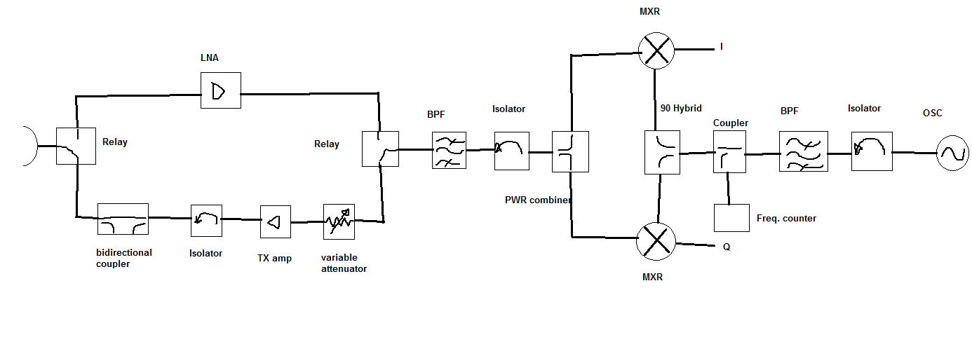
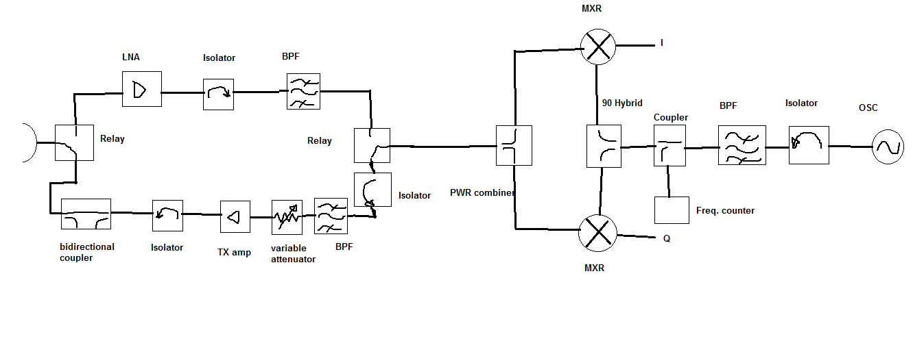
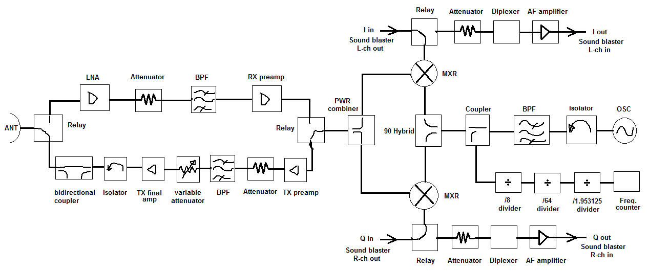
Hello, I am building a microwave Xband transceiver and I would like to know if it is a good practice to include an isolator:
1. before every attenuator
2. before every filter
3. before the antenna to the transmit side, before a bidirectional coupler, that is connected directly to the antenna.
4. after the local oscillator and before the oscillaror low pass filter.

Do I also need to include an isolator after a bandpass filter? (do the reflected power from the next stage from the filter, affect the filter parameters?)
5. Any other place to include isolators?
 

Isolators are useful for systems that are:
1)moderate to small bandwidth (less than octave bandwidth)
2)cost is not an issue (each isolator is at least $25)
3)you need very low gain ripple, or you have a very poor load impedance it has to work into

You then look at system interfaces where there might be trouble, for example where a mixer (that wants a broadband 50 ohm match) attaches to a bandpasss filter (which has a very poor match in its stopband). Adding the isolator can improve spurious signals or IP3 in the mixer, or improve conversion loss flatness.

Another example is if you have a high power transmit amplifier that could blow up if the output impedance gets poor that is attached to an antenna that might ice up in winter time.

Most systems today do not meet the 3 criteria, so you seldom see isolators in systems anymore.
 
  • Like
Reactions: neazoi

    neazoi

    Points: 2
    Helpful Answer Positive Rating
Here is my design. I am sorry for the bad drawing.
What do you think about the isolators placement?
 

Here is my design. I am sorry for the bad drawing.
What do you think about the isolators placement?

I would not put any in that block diagram, unless I was very concerned about ripple.

You can not put the isolator in between the splitter and bandpass filter that you drew if you want the receiver portion to work.
 

I would not put any in that block diagram, unless I was very concerned about ripple.

I have some isolators in hand, that is why I am asking. I think they also introduce some loss? So I would like to know if this would be better to use them at the places referred or not.
Generally speaking, an attenuator or filter will reflect back the power that is attenuated or filtered, or it will consume it?

You can not put the isolator in between the splitter and bandpass filter that you drew if you want the receiver portion to work.

Yes I noticed this error. It should be on the transmitter chain after the relay and before the variable attenuator.
Correct block diagram attached

Also, what do you think of my design? Anything better to propose?
 

Attachments

  • 87_1333450366.png
    87_1333450366.png
    26.8 KB · Views: 137
Last edited:

Usually before and after LNA there should be an insulator, to protect LNA from self-osc.
And for mixer, the same.
 
  • Like
Reactions: neazoi

    neazoi

    Points: 2
    Helpful Answer Positive Rating
Filters need to be terminated properly to achieve their design response. Variation in termination impedance due to amplifier or antenna will effect filter response. An LNA may need a non-conjugate input termination to achieve best noise figure. Both may be reasons to use an isolator.

Because of their cost and size usually everyone tries to avoid them. There are other ways to solve termination problems, like using a balance hybrid amplifier or just attenuation pads if loss of gain can be tolerated.
 
  • Like
Reactions: neazoi

    neazoi

    Points: 2
    Helpful Answer Positive Rating
Usually before and after LNA there should be an insulator, to protect LNA from self-osc.
And for mixer, the same.

For those locations, it's more common to see attenuators and diplexer filters. RF designers often use simple resistor PI pad attenuators between cascaded gain stages to improve the return loss presented to both devices. The same can be done with mixers, but I've also seen some of the sharp old pros in my company use diplexer filters to provide good termination impedance at the desired frequency (goes down the one arm of the diplexer), and the harmonics/other output tones (go down the other branch of the diplexer to a simple load resistor).
 

Filters need to be terminated properly to achieve their design response. Variation in termination impedance due to amplifier or antenna will effect filter response.
Yes, I have seen huge variations in rfsim99 on filters designed for 50Ohm, when the I/O impedances vary.
So, ideally do I need an isolator before AND after each filter?
(My RF front end, uses 50Ohm coaxial components from Narda and other manufacturers)

An LNA may need a non-conjugate input termination to achieve best noise figure. Both may be reasons to use an isolator.
So I also need an isolator between the antenna and the LNA?

Because of their cost and size usually everyone tries to avoid them. There are other ways to solve termination problems, like using a balance hybrid amplifier or just attenuation pads if loss of gain can be tolerated.
Balanced amplifiers is a good choice and they are used extensively, especially in space applications, not only for their increased gain and good I/O matching, but also for failure immunity reasons, if one fails, the others will continue to work at reduced power.
But, I think they are more expensive than an isolator, when dealing with ready-made coaxial components.

 
Last edited:

The isolator after the LNA is pretty much a waste of time and its only going to add receive losses you dont need

Dave
 

The isolator after the LNA is pretty much a waste of time and its only going to add receive losses you dont need
Dave

Yes, but there is a BPF after the LNA to restrict the bandwidth "seen" by the broadband mixers to the band of interest. This BPF will reject out-of-band signals back to the LNA, affecting it's output, unless an isolator is used there (Am I wrong?)
 

Yes, but there is a BPF after the LNA to restrict the bandwidth "seen" by the broadband mixers to the band of interest. This BPF will reject out-of-band signals back to the LNA, affecting it's output, unless an isolator is used there (Am I wrong?)

Yes, but only in the case where you have large enough out-of-band signals present coming out of the LNA, and sufficiently high reflection from the filter.

You could use some alternative methods to give you good return loss for the LNA and not install a large magnetic device. Adding a ~3 dB pad before/after amps and filters is one trick, using an absorptive filter topology is another. Most systems that I've worked with use a pre-selector filter to limit the bandwidth of the signals coming into the receiver, so you don't have to worry so much about the rejection of the following bandpass filter. It's all in how you design the gain and frequency conversion scheme... there are a myriad of potential designs.

That being said, the only place I regularly see isolators/circulators is right at the antenna port, to protect the PA; to keep it from blowing up when a high VSWR is placed at the antenna port.

I have discussed with other people as well and they have also proposed the ~3 dB pad before/after amps and filters but also the mixers. Not as much isolation, but still shows 50 ohm and usually cheaper than isolators.
Do you think that is a better solution, to include a small attenuator on the input and output of all amplifiers filters and mixers (RF/IF) in the diagram?

I worry about the LNA, adding a 3dB attenuation on the input can very much degrade the received signal and noise.

Also, The system is built using commercial SMA coaxial blocks so the impedance should be 50 ohm on the range of each block I think, so not much of a problem about impedance matching here even on the filter side?
 
Last edited:

You don't want to add loss to the input of LNA. The output impedance can usually be controlled with some resistive supplimentary termination in the output. For FET LNA design there is techniques of putting some inductance in series with source that better aligns maximum power match (best termination) with noise figure match to improve input impedance on LNA input. It cost a couple of db of gain loss in the stage.

LNA's with AGC capability are often problematic. You can control output impedance, as before, with some supplimentary resistive component in output match but input impedance usually varies wildly across AGC range. Cascode configuration with third device (looks like a diff amp config) can accomplish AGC without so much input Z change. AGC is applied to third device that steals away signal from entering top cascode device.
 

I have discussed with other people as well and they have also proposed the ~3 dB pad before/after amps and filters but also the mixers. Not as much isolation, but still shows 50 ohm and usually cheaper than isolators.
Do you think that is a better solution, to include a small attenuator on the input and output of all amplifiers filters and mixers (RF/IF) in the diagram?

I worry about the LNA, adding a 3dB attenuation on the input can very much degrade the received signal and noise.

Also, The system is built using commercial SMA coaxial blocks so the impedance should be 50 ohm on the range of each block I think, so not much of a problem about impedance matching here even on the filter side?

I don't recommend putting any additional loss in front of the LNA. As you stated, it will impact the noise figure of the system (dB for dB, at that particular location). However, after each gain stage, the impact of additional attenuation will cause less and less impact on the overall system NF.

You should add isolation-improving attenuators wherever you expect impedance interaction problems. If you have back-to-back gain stages, I'd stick a pad in between them for sure, even if it's just 2 or 3 dB. You don't need pads before and after every stage; that's overkill. Put them where you anticipate strange performance effects by presenting the input (or output) with a non-ideal 50 ohm termination impedance (amps and mixers are the two items I'd readily identify in that category).

Since you are using 50 ohm (internally-matched) "gain blocks", you can just chain things together, but additional isolation will only improve the stability of your system.... just don't go to the extreme and paint yourself into a corner by limiting your gain and noise figure performance.

That seems fair enough. For example if I use two LNAs to put a small pad between them. The same aplies if I use a preamplifier cascaded with a power amplifier I guess...

What about the mixers, do I need to put attenuation pads (coaxial attenuators 2-3db) on each port?
1. On the RF side. Coaxial attenuator
2. On the LOSC side. Coaxial attenuator
3. On the IF side. This is audio, so a 50Ohm resistance could possibly do the job? Series or shunt?

I remind you, the system is designed using 50 ohm (internally-matched) "gain blocks"

Looking at your latest block diagram, I wouldn't be very concerned about the return loss presented by the combiner or relay (unless their specs are crummy). I would make sure the return loss of the bandpass filter in the TX path is good at your image frequencies. If it's poor, you'll get those frequencies reflecting back into your mixer, which could cause performance degradation. You could either stick a few dB pad before it, or turn it into a diplexer filter... the desired freq would go out one "arm" of the filter into the PA, the other signals would go down the other arm into a simple 50 ohm resistor.
 

Looking at your latest block diagram, I wouldn't be very concerned about the return loss presented by the combiner or relay (unless their specs are crummy). I would make sure the return loss of the bandpass filter in the TX path is good at your image frequencies. If it's poor, you'll get those frequencies reflecting back into your mixer, which could cause performance degradation. You could either stick a few dB pad before it, or turn it into a diplexer filter... the desired freq would go out one "arm" of the filter into the PA, the other signals would go down the other arm into a simple 50 ohm resistor.

So you think the isolator before the tx filter is a good choice? The ssb signal generated by the mixers on TX should be powerful enough to cope with the ~0.5dB loss of the isolator anyway.

Looking at the same diagram, I am very concern if I should use the isolator on the RX side after the LNA. I think it is not needed there since the signals are of very low level and a 0.5db signal degradation is not good.

Maybe a chain of two LNAs connected together through a filter (LNA-FILTER-LNA) would be a better approach? but then again, what about reflected power of the filter back to the output of the first LNA?

I would avoid isolators AT ALL COSTS. If it is absolutely necessary, then use one... otherwise, don't. They are big, heavy and expensive. You don't see them sprinkled throughout other designs for a reason.

As for all of the other locations, it really comes down to your system's overall performance. Hook everything up and see how it works. If you can't meet your design specs, then dig down and find which part is having trouble and adjust your line-up to fix it. You said you are using connectorized blocks, so start building your circuit and see how well it performs.

You've got many ideas and recommendations, now go see if you need to use any of them or if your initial design is sufficient. They call this a spiral design... formulate idea, simulate, test, review, adjust, simulate, test, review, adjust, repeat, repeat.... until you get something that meets all of your requirements.
 
  • Like
Reactions: neazoi

    neazoi

    Points: 2
    Helpful Answer Positive Rating

This is my final design.

I have added two attenuators. One between the LNA and the RX preamp for impedance return loss problems. Also another one between the two TX amplifiers, because in the case that the variable attenuator is set to no-attenuation, there should be some isolation between the cascaded amps. I hope this is quite ok now...

My TX and RX filters have an insertion loss of 2dB. Maybe these could play the role of the small attenuators, so I do not have to use attenuators at all? (or do they needed for impedance matching reasons?)
 

Status
Not open for further replies.

Part and Inventory Search

Welcome to EDABoard.com

Sponsor

Back
Top