Continue to Site

Welcome to EDAboard.com

Welcome to our site! EDAboard.com is an international Electronics Discussion Forum focused on EDA software, circuits, schematics, books, theory, papers, asic, pld, 8051, DSP, Network, RF, Analog Design, PCB, Service Manuals... and a whole lot more! To participate you need to register. Registration is free. Click here to register now.

suggestion for a project in Verilog

Status
Not open for further replies.

Plzhelp

Junior Member level 3
Joined
Feb 18, 2012
Messages
31
Helped
7
Reputation
14
Reaction score
6
Trophy points
1,288
Location
India
Activity points
1,535
Hello people,

Can anyone please suggest me a good project which I can design using Verilog so dat I can add it to my resume. I know verilog to some extent and I want to do a project in it to build my confidence and to add it to my project.

Any suggestion will be highly appreciable.

Thank you.
 

Artqny,

I was not able to find any exact project in that link. Can you please point out any exact project for me in that link???
Thank you.
 

OFDM modulator design can be one idea
 
Electronica,

Sounds very good.. Thank you.. Can you give me some further input on this Project???

---------- Post added at 23:18 ---------- Previous post was at 23:00 ----------

Electronica,

I dont have any idea about what OFDM Modulator is all about. I went through a basic description of it and found it really good. I need your complete assistance to help me out with this project from the scratch. Help of any kind will be highly appreciated.

Thank you in advance..
 

do a FSM project. decide and design yourself a cofee/ticket vending machine in block by block and make it complex and then build it...
 

Graphene,

Thank you for your suggestion but I have already done a simple coke winding machine project.. Although it was not a very complex design, but I dont want 2 do that project again... Can you suggest something else which can be done..??
 

well make a 32 bit addder and also 32 bit subtractor and multiplex them.... make a main FSM with 4 inputs, 2 of which comes for the odd and even partiy chekced output of this multiplexer ... the remaining 2 being the SONAR inputs from other source (for now consider 2 random inputs) ... the output of the FSM viz Sonar op and parity chekcers output are AND'ed and again sent back to the sensor.. draw it, and lets communicate further if this Idea wud make sense to you...
 
Graphene,

Sorry for the late reply.. Started working on your suggestion.. Sounds good.. Practical application of this whole project is??? Well working on 32 bit adder/subtractor now.. I didn't understand the FSM part in the project.. Will attach the code and send it you once I am done with it..
Thank you for helping me out.. Need further assistance..
 

Graphene,

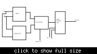
The FSM you talking about is partly a parity checking FSM, the input of which is connected to the output of multiplexer. But you r talking about 2 inputs from the multiplexer. How is that possible??? I am little confused in that part. Kindly explain. Attaching a diagram for the simple design flow of the project as per my understanding. Please do the necessary correction and let me know so that I can work ahead.


well, till what u did is correct... my mistake about 2 vaules from muxx...
out top module has 4 inputs, 4 outputs(to begin with).....
1)here this particular output from parity checker, an one-bit value is input1,
2) input2 and input3 are two other random inputs (outputs of 2 other module which I shall describe later) and
3) one manual input(input4) used only during the start of the system...

inp1 makes out1 high and so on for out2 and out 3...
.
but out4 makes a global reset of all (adder, subt, mux, par checker, top module, other blocks which shall follow (i lll give them once u frame this architecture))
.
if any confusion in understanding lemme know... so try till this...

---------- Post added at 14:15 ---------- Previous post was at 13:45 ----------

to add more, I cant give u the exact working protocols...
.
so the reamingnin 2 blocks works like this..
.
1) trans block.... gets tr_inp(out2) from the top module.. and upon High the sonar works (u may

consider s signal high is triggered) and d same is passed to inp3

2)reciever block inp3 makes the out3 enabled, which in turn enables this block ON. .
once some condition is satisfied (lets say something detected (i wont give u exact

infos)), it sends a signal High to reset of the top module.
.
and all the processes begin again.
.
for a viewpoint u have one main block and 2 blocks of sensors as mentioned in this post

and other blocks u had already made..
.
I think for practice purpose if u can make this happen it will b great to begin with...
. clarifcations welcome asap...
 

Graphene,

No issues... Thanks for communicating your ideas so fast... I will now right the code for the diagram I sent you.. Once that part is done we can go ahead with the further part of the project which you mentioned in your second post.. Just a small thing to ask... Adder and subtractor thing, should I make it for signed numbers or unsigned numbers??? Reply to this question asap so that I can start coding for the diagram and we can go ahead with the project asap..

Thank you..
 

Status
Not open for further replies.

Part and Inventory Search

Welcome to EDABoard.com

Sponsor

Back
Top