Continue to Site

Welcome to EDAboard.com

Welcome to our site! EDAboard.com is an international Electronics Discussion Forum focused on EDA software, circuits, schematics, books, theory, papers, asic, pld, 8051, DSP, Network, RF, Analog Design, PCB, Service Manuals... and a whole lot more! To participate you need to register. Registration is free. Click here to register now.

Choosing MOSFET for my boost converter

Status
Not open for further replies.
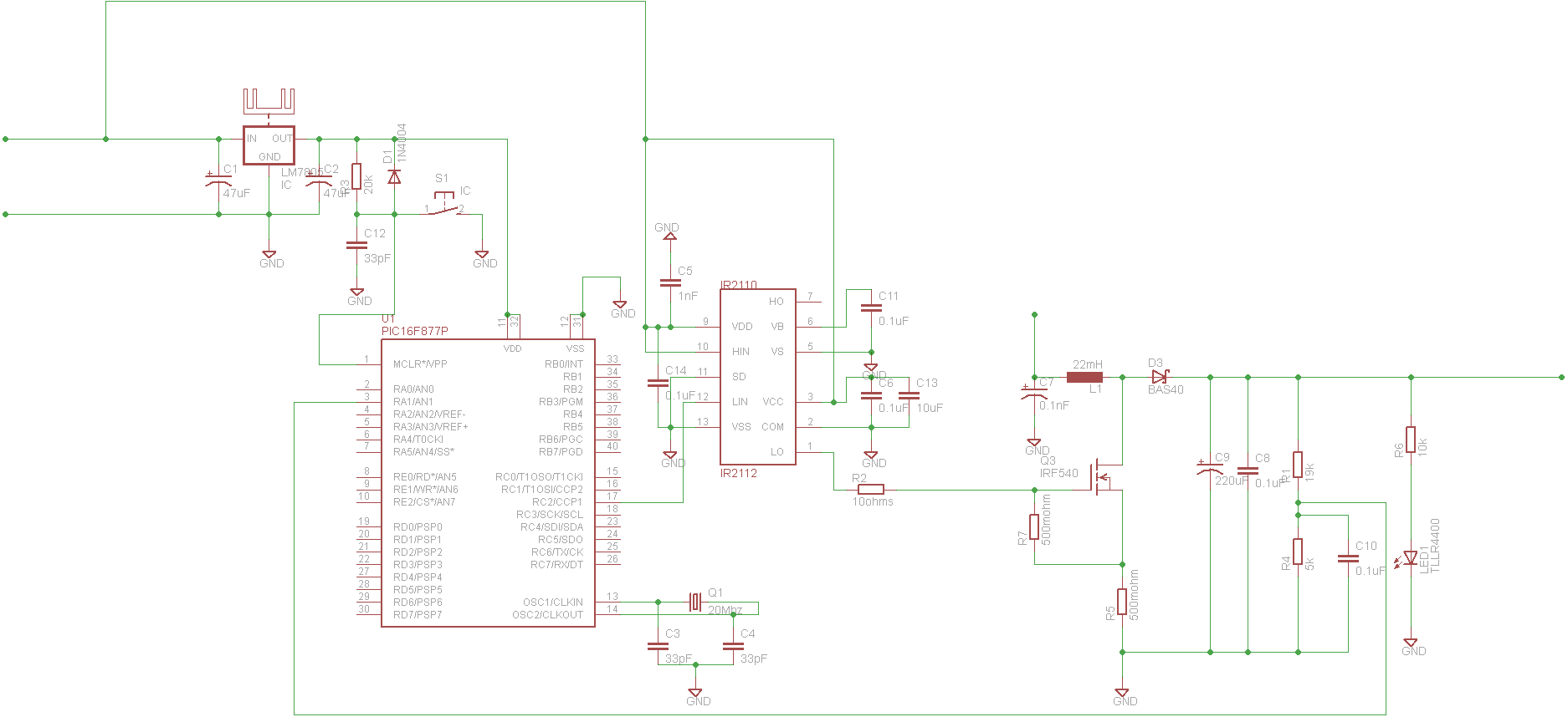
thanks.. i came across this boost converter circuit that uses some other mosfet and drivers. i need it modified to suit my application.. i have very little time to finish the project so i need some help here.. i m currently doin the programming for the PIC control of my boost converter.

View attachment boost converter.bmp
 
Which driver did you choose? Did you go through the datasheet? Are you done with the coding?

You can take the MOSFET, inductor, capacitor etc - ie the power boost stage - from this circuit as it is pretty much the same for all boost converters. You'll need to change the driver stage, using your driver. Also, change the feedback section - here a simple resistive divider is used, so you might need to change it depending on the code; the values are blurred in the picture, so can't read the value.
 

i did a circuit using cadsoft eagle. can u check it and tell me any mistakes.. thank you.. all the details u want are there..

---------- Post added at 12:31 ---------- Previous post was at 12:28 ----------

the site wont let me upload sch files.. what should i do??
 

i got t.. i can export the circuit file to an image.. can u check the circuit and tel me if there are any problems with it??
 

Connect +12V or more to pin 3 (VCC) of IR2112.

Change value of R2 to around 10Ω to 22Ω. Connect a 1k resistor between the gate and source of the MOSFET. Using a 10µF capacitor in parallel with C6.

Value of L1 seems too large.

Why are you using a transzorb for D2? Use a schottky instead.

Use a 0.1µF ceramic capacitor across VDD and VSS.

If you're not going to use current-sensing, you might skip out R5.

Hope this helps.
Tahmid.
 
ya it helped a lot.. can you just tell me what i need to add if i am going to use current sensing.. i know it involves op amps but i m not sure..and also suggest a value for the inductance.. i will make the changes you asked and attach the diagram soon.. thanks a lot

Sai
.
 

This is the boost converter circuit with the changes u asked.. i wanna know what to do for current sensing.. pls reply soon thanks

Sai


Change the value of R7 to 1kΩ.

Use R5 for current sensing. Measure the voltage across R5 using the PIC ADC and determine what is to be done at which current setting in the code. V=IR, so I=V/R. Use this information in the PIC code to determine the current by measuring the voltage.

Ensure that you connect a small RC filter. You can use a 1kΩ resistor and a 0.01µF or 0.1µF capacitor.

Hope this helps.
Tahmid.
 
ok.. thank you.. so the RC filter is the low pass filter everyone keeps talking about........
 

ok.. thank you.. so the RC filter is the low pass filter everyone keeps talking about........

Yes. The values are not so critical and if any problem arises, you can tweak the values through trial and error. 1kΩ resistor and a 0.01µF or 0.1µF capacitor is a good starting point.

Hope this helps.
Tahmid.
 
Hello People
I have a similar doubt in same domain
my question is : since we know how to control output voltage of boost converter, but what are the factors which dictates output power, i.e. output current. Is it only the capacitor which determines it?
and in case of a mosfet switch, mosfet should be choosen to match the corresponding current?
 

If output current is 0.3A at 24V output voltage, the output power is 24*0.3=7.2W

Peak current = (5.5 * Power output)/(Minimum input voltage)

So, you should choose a MOSFET with a current rating higher than the peak current (you should keep a significant margin), with a low enough RDS(on) to minimize losses.
Conduction loss in the MOSFET = (I^2)*R. R here would be RDS(on), I would be current flowing through the MOSFET.

Hope this helps.
Tahmid.

Hey Tahimd,
Can I ask how do the 5.5 get from in your formula Peak current = (5.5 * Power output)/(Minimum input voltage), I really appreciate if you can quota a detailed formula or a something else. I'm confused with this stuff for a long time.
Thanks!
 

..... the strange part is my input is a solar panel which is supposed to be a 12V 20W panel but its giving me an output of 24 v in the sun.. can anyone explain why?? ................
The reason the rated voltage is about 1/2 the maximum voltage is that, from the Maximum Power Transfer Theorem, the maximum output power from the solar panel occurs when the load resistance is equal the panel internal resistance. This will give an output voltage of 1/2 the open circuit voltage of the panel. Thus MPPT power supplies maximize output power by automatically adjusting the load so that is always equals the panel impedance.
 

Hello ,
I am trying to build a sepic converter for Mppt charge controller and I have simulated the same in NL5 simulation and Proteus ..They seem to be working fine..I am using IRF540 ...Which gate driver to use ?ucc2701,Ir2110,Ir2184 or Uln2803...??
 

Attachments

  • Screenshot 2014-01-31 08.12.35.png
    Screenshot 2014-01-31 08.12.35.png
    168.6 KB · Views: 83
  • Screenshot 2014-02-20 17.19.38.png
    Screenshot 2014-02-20 17.19.38.png
    178.6 KB · Views: 84

Status
Not open for further replies.

Similar threads

Part and Inventory Search

Welcome to EDABoard.com

Sponsor

Back
Top