Continue to Site

Welcome to EDAboard.com

Welcome to our site! EDAboard.com is an international Electronics Discussion Forum focused on EDA software, circuits, schematics, books, theory, papers, asic, pld, 8051, DSP, Network, RF, Analog Design, PCB, Service Manuals... and a whole lot more! To participate you need to register. Registration is free. Click here to register now.

Help me add Tamura 3FL16-350 to a PCB layout

Status
Not open for further replies.

brosskgm

Member level 4
Joined
Dec 9, 2010
Messages
76
Helped
2
Reputation
4
Reaction score
2
Trophy points
1,288
Location
California, USA
Activity points
1,853
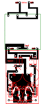
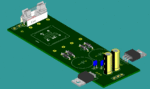
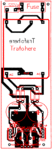
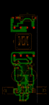
Need help from someone that knows PCB design and can work with a .lay file. I was given a pcb file (.lay file attached in zip) for a power supply and needed a transformer to tie on to it.

I have a 3FL16-350 Tamura datasheet is attached also that I was told would be an excellent choice.

I don't understand how to work in design so if anyone can give assistance to put the Tamura on this would be great.

Thanks in advance for any help.
Bob
 

Attachments

  • 3FL16-350 Tamura Transformer.pdf
    378.8 KB · Views: 95
  • 7805_7905_Voltage_Regulator.zip
    14.5 KB · Views: 64

Re: +/- 5V power supply.

:)

Try this way:
 

Attachments

  • Trafo 1.GIF
    Trafo 1.GIF
    48 KB · Views: 96
Re: +/- 5V power supply.

Thank you so much. This will give me something to work on.
All I have to do is figure out how to get this on the PCB board.

Thanks again
Bob
 

Re: +/- 5V power supply.

On a second thought, :cool: there’ s a need to use a fusible unit in the primary circuit and maybe it’s better to rotate the LM7905 integrated circuit as this may require some small heat sinks.
 

Attachments

  • power source 5V.GIF
    power source 5V.GIF
    21.6 KB · Views: 92
  • pcb 3d 1.GIF
    pcb 3d 1.GIF
    24.3 KB · Views: 86
Re: +/- 5V power supply.

Hi mister_rf,

Thank you for this.

Is there a chance you could put this in a .lay file? I have a couple small heat sinks so that's not a problem.

Thanks
Bob

---------- Post added at 16:27 ---------- Previous post was at 16:19 ----------

I do have pictures of the unit I pulled this transformer out of if that will help. It's an Adtran DSU 56/64 1997 back during the 56K internet circuit days. It was mentioned just cutting the area out and use that but not knowing enough I didn't.

I do have another one of these that I haven't tore apart yet if the complete setup is needed.
 

Re: +/- 5V power supply.

:-D

Try adjusting this PCB for the correct transformer mounting footprint …
 

Attachments

  • 5 V power.GIF
    5 V power.GIF
    48.4 KB · Views: 83
  • test 5V_v2.rar
    17.7 KB · Views: 60
Re: +/- 5V power supply.

Ok thanks. I'll see what I can do. I'm not sure the viewer will let me do that but I'll find a way to work with it.

Thanks again
Bob
 

Re: +/- 5V power supply.

Hi,

I printed out your .lay file, you have the PCB footprint perfect for the holes.

Thanks
 

Re: +/- 5V power supply.

mister-rf, where you make the PCB layout (software) n how make it 3D,? I use Eagle software, please tell me how.
 

Re: +/- 5V power supply.

I just got all pieces to put this together.

It keeps blowing the fuse. Any suggestions were to look?

I have pins 1234 on the AC in.

Thanks
Bob


:-D

Try adjusting this PCB for the correct transformer mounting footprint …
 

Re: +/- 5V power supply.

I have a question about part of this.

The datasheet for the 3FL16-350 Shows pin 1 & 3 together and 2 & 4 together.

But in the datasheet Pin 3 is the last one and pin 4 is the third one, as with the out put 5 & 7 are on the ends and pin 8 is the third one.

1 5
2 6
4 8
3 7

Could this be causing it to heat up and blow the fuse?

The datasheet is attached a couple entries above. If it's not there I can send it again.

Thanks.
Bob


:-D

Try adjusting this PCB for the correct transformer mounting footprint …
 

Yes, now I have realised my mistake. Mea culpa... Reverse transformer pins 3 and 4, also pins 7 and 8 and later try to test the circuit by connecting series some light bulb (110v/40W-60W.
 

Attachments

  • Modified power source.gif
    Modified power source.gif
    29.2 KB · Views: 129

I'm glad to hear it wasn't all me.

Would you be able to send a new .LAY file? I only have the viewer/printer.

Thanks
Bob


Yes, now I have realised my mistake. Mea culpa... Reverse transformer pins 3 and 4, also pins 7 and 8 and later try to test the circuit by connecting series some light bulb (110v/40W-60W.
 

mister_rf,

Thanks. Would you by chance have an updated .LAY file?, I'm only able to read them. Can't edit them.

Thanks
Bob


Yes, now I have realised my mistake. Mea culpa... Reverse transformer pins 3 and 4, also pins 7 and 8 and later try to test the circuit by connecting series some light bulb (110v/40W-60W.
 

Files attached. :-D
 

Attachments

  • layout_2.rar
    16.7 KB · Views: 54
  • tamura.GIF
    tamura.GIF
    50.8 KB · Views: 81
Status
Not open for further replies.

Part and Inventory Search

Welcome to EDABoard.com

Sponsor

Back
Top