Continue to Site

Welcome to EDAboard.com

Welcome to our site! EDAboard.com is an international Electronics Discussion Forum focused on EDA software, circuits, schematics, books, theory, papers, asic, pld, 8051, DSP, Network, RF, Analog Design, PCB, Service Manuals... and a whole lot more! To participate you need to register. Registration is free. Click here to register now.

Little COnfusion about Antennas,Monopole Antenna

Status
Not open for further replies.

Qube

Member level 5
Joined
Nov 10, 2010
Messages
80
Helped
7
Reputation
14
Reaction score
7
Trophy points
1,288
Activity points
1,896
Hello friends,i was reading about monopole Antennas, most popular monopole antenna's are Whip Antenna,which are mounted on Cars for its radio receivers...
I read, monopole Antenna will have a GROUND PLANE, here my doubt arises...

Imagine i have a transmitter circuit and i want to use the monopole Antenna with my transmitter,i will connect the out put from the collector of last stage transistor through a capacitor to the monopole Antenna, and i was thinking should the ground plane should be connected to the NEGATIVE point of the transmitters power source???


Or else the ground plane should not be connected to transmitter and should not be connected to the Antenna too but it has to be placed under the antenna where the Antenna stand perpendicularly to the ground plane to work as a Signal reflector???


Plz help me understand this..
 

The antenna ground plane will ideally be connected to the ground on the last active device in the transmitter, or the first active device in the receiver, chain. So if you have a transmitter with a power fet at the last stage, the source of the FET is attached with low inductance/resistance to the antenna ground plane.

Alternatively, you can hook the transmitter to a coaxial cable, and the coaxial cable has the center contact go to the monopole whip, and the ground shield go to the ground plane.

If you assume the negative is a good ground point, you are ignoring the various wire inductances and resistances in series.

Glad that i got some help :)

And I didn't understand that highlighted sentence,Wat does the Source of the FET mean??

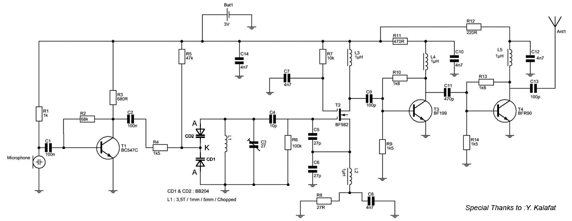
The schematic uses a NPN transistor,so the source of the NPN is attached with low inductance/resistance to the antenna ground plane.

Is it the signal source of the NPN transistor or the Power source of the NPN??or i should connect it to the negative source of the circuit??

To make my question easier,ill post this Random sample schematic,the monopole antenna is connected to the collector through a 100p cap,And can you please point out where the ground plane should be connected??

3v_fm_transmitter_for_short_distance_88Mhz_to_108Mhz.gif
 
Ty for your help biff and volker,i'll try it and if i don't encounter and problem ill mark the thread a solved
 

Status
Not open for further replies.

Part and Inventory Search

Welcome to EDABoard.com

Sponsor

Back
Top