palmeiras
Full Member level 6
- Joined
- Feb 22, 2010
- Messages
- 375
- Helped
- 61
- Reputation
- 122
- Reaction score
- 50
- Trophy points
- 1,308
- Location
- South America
- Activity points
- 4,199
Hello guys,
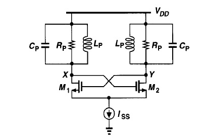
Could you, please, help me understading the basic LC oscillator?
1-Who does it works?
2-If a voltage pulse (not oscillation) is inject in node X, will this circuit oscillate?
3- Is there any text showing a step-by-step sizing process?
Thank you very much,
Could you, please, help me understading the basic LC oscillator?
1-Who does it works?
2-If a voltage pulse (not oscillation) is inject in node X, will this circuit oscillate?
3- Is there any text showing a step-by-step sizing process?
Thank you very much,
")