Continue to Site

Welcome to EDAboard.com

Welcome to our site! EDAboard.com is an international Electronics Discussion Forum focused on EDA software, circuits, schematics, books, theory, papers, asic, pld, 8051, DSP, Network, RF, Analog Design, PCB, Service Manuals... and a whole lot more! To participate you need to register. Registration is free. Click here to register now.

NiMh batterz charger nedeed

Status
Not open for further replies.

nmbg011

Member level 3
Joined
Oct 22, 2011
Messages
59
Helped
2
Reputation
4
Reaction score
2
Trophy points
1,288
Activity points
1,687
Hi all,

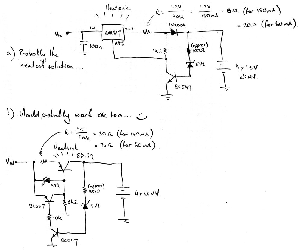
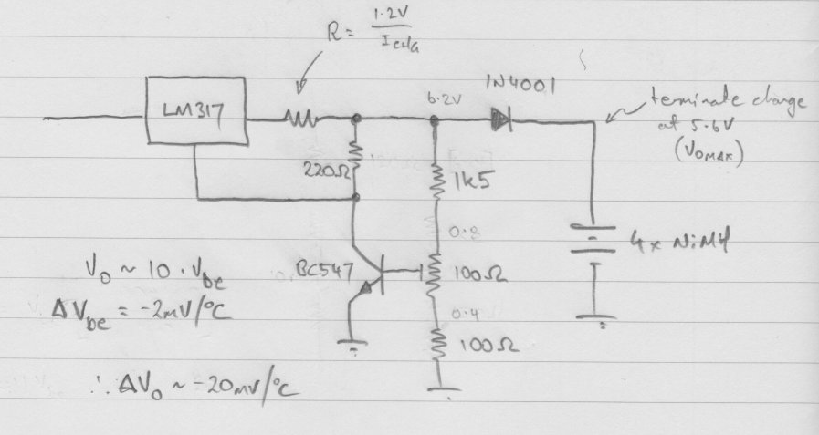
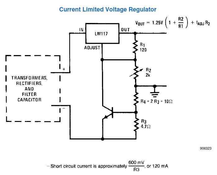
I need NiMh battery charger, with constant current, without MAx... and such IC, just make by transistor.

I need 150mA and 60mA optional charging current. Charger should stop at desired voltage level for 4xAA or 4xAAA 5,8V-6V
 

Heya nmbg011,

I just sketched a couple of simple options that might help you out... the first circuit would be my preference because the LM317 is inherently rugged and lends itself to easy heatsinking and can cope with a wide range of input voltages. Option b) adheres to your "strictly transistor" goal better though - your choice :)


I won't go into the detail of their (intended) operation here as you'll see the charge 'cutoff' configuration consisting of the zener/resistor/BC547 is common to both approaches, and I have previously described its operation in this thread: https://www.edaboard.com/threads/237775/. The remaining components form a conventional linear current source to supply the requisite charging current. This current is configured to reduce upon conduction of the BC547 transistor.

Hope that helps - let me know how it goes or if you get stuck!

P.S. Ooops! Just noticed that I wrote 'BD139' on the scanned sketch. I meant to write the part number of its complement - the BD140. (i.e. yes, it's meant to be PNP!)
 
Last edited:
Dear thylacine
Hi
As i can see at your circuit , you used a pnp transistor , but BD139 is NPN ( you have written bd139 near of that .) i think your mean was BD 140 or BD 138 , isn't it ?
Best Regards
Goldsmith
 
Hey ThyLacine75 you make nice work I go to try this now, thanks again.

I will try and say result of that.
 

Thanks Goldsmith ... I'd only just spotted my blunder myself a few minutes earlier and thought a text edit was easier than rescanning the attachment :)
Cheers for pointing it out though - I'll give my next late night sketch a cooling off period (and a better proof read) next time!

J ;)
 
@ThyLacine75 I try a.) circuit but no current and voltage termination. I try 82R 100R 120R on zener 5,1 and bc547 base.

I try different BC546 and BC547 and tha same.

I will try to replace zener.

I replace zener and now get termination of charging but charging is terminated completely, when I disconect zener charging go. I discharge battery to 4V and charging dont start. Old zener was probably damaged.

Resistor of zener is 100R, also tryed 47R, 82R, 120R and 300R, but charging dont start. Also I tried to put zener 3,3V but the same no charging, and when disconnect zener charging starts. :| Also tried to put higher resistors on zener 1K, 2,7K, 3,8K 4,7K and the same charging dont starts, when remove zener or resistor, charging starts.:-?

I will try to put some higher zener value then 5,1V (with resistor 100R):
Tried 5,6V without success.
Tried 8,2V charging is started, but voltage is too high for 4 NiMh.

Tried 6V zener and charging started, but with no full current.
Full current is set at 350mA (for testing) and with zener 6 current starts from max 90mA and goes down to 60mA@5,35V 40mA@5,42V 10mA@5,50V 0mA@5,55-5,6V

How this happen? :|:-?:?:
 
Last edited:

Hmmm - what a turd... nice job characterising the circuit's behaviour though nmbg!

From the measurements you've made, it sounds you're being plagued by zener leakage currents (which is further compounded by having a good, high gain BC547).
All (practical) diodes allow some reverse current to flow at reverse bias less than the breakdown voltage, at which point it increases rapidly. From what you've described, it would appear that your BC547 is being turned on sufficiently from the reverse leakage current to sink enough current through its collector and shut the LM317 down. As the zener breakdown voltage is increased the leakage current will be reduced (for a given reverse bias), which is why I'd figure the circuit struggled into life with zeners > 6.0V.

This gives us two options:
1. Reduce the effect of leakage currents, or
2. Decrease the rate at which the LM317 is shut down via the BC547.

The first option is probably the best, and one approach would be: Add a 470R resistor between the transistor's base and ground (the emitter). This means the transistor won't turn on until ~1.3 mA of zener current (well above typical leakage currents) is flowing.

The only possible downside to this is that your batteries can discharge via this path if their voltage is above the zener voltage. If this is a problem, adding a series 1N4001 (or similar) diode between the charger an the batteries will fix things (and increase the charge termination voltage by ~0.6 V, which may necessitate a zener value change).

Let me know how that goes for you - apologies I'm not in a position to prototype it myself at the moment, but with detail like your previous post I'm sure we'll sort it out in short order!
 
TheLacine75 you are the best!! this works!! :grin:

I put one additional diode in front of batteries.

I play with resistors and adjust nedeed voltage, here parameters:

Zener 5,1V

Zener resistor :
47R 5,37V Off
100R 5,45V Off
120R 5,49V Off
200R 5,59V Off
330R 5,78V Off

All works big thanks my friend!!! :grin::grin::grin::grin:


Can we improve now this circuit with :

1. Can we make that LM317 stay off on end of charging cycle? If new cycle needed some taster must be pressed. With some capacitor on transisitor base, or similar thing,...

2. Add status charging red led, and green led when charging cycle is ended.


Current circuit :

circuit.png
 
Last edited:

That's wonderful news nmbg! Well done - and my pleasure :)
(Nicely drawn too, btw :)

Yes, we can certainly add the extra features you want (I'll sketch them up later today). In the meantime, adding a red charging LED is a snap - simply connect the LED from the output of the LM317 to ground via an appropriate (~330 - 560R) resistor. When charging, this point will be equal to the battery voltage+(1.2 to 2.4) V, thereby lighting the LED. When the BC547 conducts this point will fall to ~1.2V which is below the LED's forward voltage, thus extinguishing it.
 
Thanks again thylacine,

I make graph of charging :

Graph.jpg


How to make constant current of charging from start to end.

Why BC547 pass current under zener voltages? How can we make him to open only on zener breakdown.
Can we add somehow additional transistor and his base to existing bc547 collector to just switch LM317 on and off.


Thanks again, for your commitment.
I'm rookie.
 
Last edited:

Dear nmbg011
Hi
If you want charge the battery , the current of charge should not be constant . when the input resistance of battery going to change, the current of charge should become lower.
Good luck
Goldsmith
 
To reduce the current in R1, you may like adding another NPN transitor to form, with Q1, the Darlington configuration. In this case R1 and R4 could be made of higher resistance but the ratio R4/R1 should be made higher as well since R4 will see 2*Vbe instead of 1.

Added:
I missed the point that also the zener current will be reduced too. The advantage of this circuit is its simplicity so it can't be perfect :)
For instance, you may like testing (simulating) the charger circuit for different temperature unless it changes a few degrees only.

Added:
You may like using an opamp IC like LM324 (or equivalent) if you are familiar with.
 
Last edited:
Dear nmbg011
Hi
If you want charge the battery , the current of charge should not be constant . when the input resistance of battery going to change, the current of charge should become lower.
Good luck
Goldsmith

Hi,

NiMh and older NiCd can be charged with constant current without problem. If we disconnect R1 or zener charger will charge with constant current, and point is to cut when voltages is on max for batteries, for NiMh 1,5V per cell or less.
 

How to implement LM721 into this to sense voltage level and cut LM317 ?
 

I think you meant by LM721 an opamp IC... right?
Let us assume you can have an LM358 IC (it is a low power dual opamp).
Let us also assume we let this IC cut the charger current completely when the battery is charged.
But the opamp IC has to be connected to the 12V supply all the time hence the supply current cannot drop to below about 1mA at best... Is this ok for you?

Added:
I forgot asking you if your 12V supply is regulated or not.
If not, we will need to add a regulated reference voltage. Obviously it will need a current but we can try isolating it from the 12V supply with LM317 after full charge.

Hint:
The on/off electronic switch could be a PNP transistor driven by the opamp output via a resistor (actually two).
 
Last edited:

Hey gang - back again (accursed timezones and the demands of a real job! ;)
OK, to answer some of what's happened in the last little while:

nmbg - That was an interesting plot of Ichg vs Vout! And yes, I see the taper from full current to zero over ~600 mV. In practice, this isn't so bad as it will just extend the battery charging time at the point when the cell's ability to absorb charge (i.e. near the end of the charge cycle) is diminishing anyhow. Given we're not temperature compensated (more on this in a sec, KerimF), this is quite acceptable. But yes, I agree, it'd be nice to do better :)

goldsmith - You are certainly correct about the batteries' internal resistance changing. The finite battery impedances mean the charge currents do naturally diminish when charging from a constant voltage source. The goal of this charger is a little of both - a constant current source capped at a certain voltage, so we expect to see the current taper right at the end point. Until that point though, we'd hope for a constant current (which NiMH/NiCD batteries certainly don't mind) - and that point is a little 'broader' than hoped here...

To your question nmbg: Why does the BC547 pass current under the zener voltage?

Predominantly, because low voltage zeners s.u.c.k.! That, and the currents we're talking about here are actually tiny. As caused us grief earlier, all zeners exhibit leakage current at reverse bias below breakdown. Have a peek at a [random] zener datasheet (https://www.fairchildsemi.com/ds/1N/1N5225B.pdf) - some of the devices LEAK > 100 uA at only 1V reverse bias! (Lower voltage devices are ALWAYS worse). The breakdown "knee" is also pretty poorly defined in low voltage zeners, and especially so at tiny currents. The datasheet parameter Zzk refers to the 'effective resistance' that appears in series with an otherwise ideal diode for the current (Izk) shown. For devices < 5.6 V (where the physics of the breakdown mechanism change), this parasitic resistance is ~1 kohm, which significantly affects the transistor base current in exactly the same manner as the resistor R1.

This problem is further compounded by the gain of Q1, which (due to its effective current gain) can sink ~100x the current via its collector as the zener provides to the base. Given that drawing only ~100uA from the LM317's adjustment pin will pull the output voltage to the minimum of 1.25V, this process is achieved with only ~1 uA of base current. Hence, adding the resistor R4 was essential to better define the turn-on point of Q1. Actually, let me digress briefly to talk about transistor operation here, as it will make it easier to discuss temperature stability in a moment :)

Unfortunately, the hand-wavy discussion of collector vs base current I just participated in is seen all too often in transistor analysis. In *some* cases (like illustrating the point above), it's a useful guideline. Strictly speaking though, the transistor is a transconductance amplifier - a complicated way of saying the CURRENT in the collector is controlled via the VOLTAGE across the base-emitter junction. It's not a 'current amplifier' (even though it can be *configured* as such). There's oodles of maths on the net if you're interested, but you can go a long way with a few rules of thumb:

1. Vbe has to be ~0.6V before any collector current starts to flow.
2. The collector current increases approximately 10x for every 60mV of Vbe increase
3. The Vbe temperature coefficient is -2mV/degree C

Rule 1 is why we added R4. By forcing the zener to develop a *voltage* across the resistor, we could more precisely define the turn-on of the transistor. Rather than relying on poorly defined (and tiny) zener currents, we could now count on ~600 mV having to be developed before anything would happen. R4 is relatively small, so this amounts to a macroscopic zener current. Much better! Once the transistor *began* to conduct, sure, a tiny base current is required to sustain the collector current, but this is only ~1uA, a factor of 1000 times smaller than the zener current required to develop the 600 mV across R4. Thus; a) we don't notice it, and b) who cares if it was 50x bigger or smaller? It's tiny! We have thus gained some independance from slight variations between zener diodes!

OK, back to the excessive charging current taper observed.

I suspect this will have a lot to do with the zener characteristics, and the parasitic resistance (mentioned previously) in particular. There's a couple of possible strategies around this:

a. Remove the parasitic resistance,
b. Insert a voltage reference and a high gain 'comparison' device to effect a narrow voltage decision threshold.

I must admit I'm a little underwhelmed (and I've learned a valuable lesson!) with the performance of the zeners we've seen here... so what if we got rid of it and relied solely on the transistor's Vbe as the voltage-cutoff-determining-value? Here's my thoughts:


I've added a 100R trimmer on the base to allow the threshold to be set, since the end-point is determined by the exact Vbe voltage that draws sufficient current from the LM317 to shut it down, multiplied by the voltage divider network by ~10x. Now, the effects of the transistor's temperature coefficient (which were/are present in the original circuit, just swamped by the zener's characteristics) are more clearly visible... enter BJT rule 3. The Vbe required to pass a given collector current DECREASES by 2mV for every degree (C) of temperature rise. Therefore the end-voltage will appear to decrease by ~20mV of ambient temperature increase. For charging batteries at room temperature, this is probably OK. Alas, it's also the best we can do with a single transistor (without temperature compensation networks).

If we added another transistor (or more), we could start down the road of approach b) - by constructing a differential amplifier to 'compare' a voltage reference (which could be a precision bandgap reference, or just a [comparatively well behaved] high voltage zener) with the output voltage and abruptly switching the LM317 on/off. While a fun exercise in BJT's (!), KerimF's approach is probably the better - grab an op-amp like the LM324 (which is especially nice since its common mode voltage ranges are well suited for single 12V supply operation). The LM324 is happy with a very wide range of rail voltages, so you could omit adding a regulated supply for simplicity. While you could add a series PNP switch (or FET) ahead of the LM317, I'd suggest retaining the current BC547 approach to shutting the LM317 down, since a series transistor has to pass the (higher) charge current (and dissipates [possibly negligible] additional heat to dispose of). Yes, the op-amp could certainly control either approach though :)

It's all a matter of how much complexity and what tradeoffs you're willing to make!
Apologies for the novel, but I'll leave you with a circuit that leaped at me that would probably also work for you nmbg and is yet another interesting permutation of transistor + LM317:
(Lifted straight from page 21 of the datasheet: https://www.ti.com/lit/ds/symlink/lm117.pdf)


The resistor values shown are pretty close to the currents you're after, and the voltage is set by appropriate choice of R2. The caveats to beware are: a) The input supply 'ground' is different from the battery 'ground', and R3/R4 will dissipate a few hundred mW (depending on your charge current).

*phew* Hope there's something useful to you in all of that! Good luck! :)
 
Hi,

Thylacine75 I try first solution from post #16 but no cut out, he stays about 5,90-5,93 with about current 70mA, with pot on max left, with pot max right he goes over 6V. I dont have pot 100R, but I use pot 300R with 150R parallel to get 100R pot.

I limit current from LM317 to max 100mA.

Also tryed 300R and 68R to get 55R pot, but the same, current is 80mA and increasing slowly, on other side pot goes to max limited current and higher voltage. He constantly increasing voltage, I turn pot on left side to decrease maximum voltage and put additional three diodes before batteries but voltage goes to 5,88V and steal increasing slowly at current 70mA. Three additional diodes plus one first from your original circuit diagram.

I will try to decrease 1,5K resistor to see result.
I put 1K resistor and current is 20mA at 5,66V, 20mA at 5,72V. I think that he floating at 5,70-5,72V at 20mA.
I will try now 560R resistor. With 560R current is low almost 0mA and voltage is on battery level, like no charging at all.


My first idea is to make easy to build NiMh charger with few parts on mini pcb, but maybe is better to do this with voltage comparator like LM741 or similar. How We can do that ? (Constant current charging and at 5,7-5,8V to cut off voltage and current).
 
Last edited:

Status
Not open for further replies.

Similar threads

Part and Inventory Search

Welcome to EDABoard.com

Sponsor

Back
Top