Continue to Site

Welcome to EDAboard.com

Welcome to our site! EDAboard.com is an international Electronics Discussion Forum focused on EDA software, circuits, schematics, books, theory, papers, asic, pld, 8051, DSP, Network, RF, Analog Design, PCB, Service Manuals... and a whole lot more! To participate you need to register. Registration is free. Click here to register now.

Transimpedance Lock in amplifier

Status
Not open for further replies.

frankqt

Member level 4
Joined
Jan 22, 2012
Messages
72
Helped
0
Reputation
0
Reaction score
0
Trophy points
1,286
Activity points
1,929
I like to build a lockin amplifier for an optical application. I currently have a system but the SNR is not enough and based on my research lock in amplifier is the solution. I control both the source (laser) and sink (PD and transimpedance) in my handheld device.

- I will use my processor's clock output (programmable, ARM processor) as the primary clock. The reference frequency is 5MHz (I need a very HF due to nature of my application)

- I have a laser that I will modulate using a Sine Wave (5MHz) (A low pass filter and a current modulator using Opamp) - I can get this working

- I now need to build the receiver. I have already built a standard Transmimpedance amplifier that has a good performance using 400MHz GBW opamps. It is a simple two stage inverting amplifier with a gain of 1M. I like to feed this Opamp output to a circuit along with the 5MHz reference signal and get the output. I am interested in the amplitude of the signal only.

How can I approach to the receiver?

Thanks
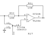
 

At 5 MHz you are going to have a significant phase shift in the lock-in loop.
If you are going to use a single demodulator you also need a programmable phase-shifter for the reference signal: you tune the phase shift to get the maximum demodulated signal.
Otherwise you may use an I/Q demodulator in order to get the quadrature component.
In this case you need a 4x reference (20MHz) or a 90° shifted clock.
 

Thanks Dave. Could I use my processor as the phase shifter. I generate my sine wave using processor (from a square wave), I can similarly generate a second sine wave, same in frequency and but shifted in phase.

In other words, during development on the bench, before I enable lock in, I optimize my software to make sure the phase shift from second source is identical to the initial transimpedance amplifier and filter phase shift.

If this approach works, all I would need would be an analog multiplier and low pass filter. Do you agree?

At 5 MHz you are going to have a significant phase shift in the lock-in loop.
If you are going to use a single demodulator you also need a programmable phase-shifter for the reference signal: you tune the phase shift to get the maximum demodulated signal.
Otherwise you may use an I/Q demodulator in order to get the quadrature component.
In this case you need a 4x reference (20MHz) or a 90° shifted clock.
 

If this approach works, all I would need would be an analog multiplier and low pass filter. Do you agree?
Indeed. Also, if you have some noise margin, you can simplify the circuitry using square wave demodulation - the demodulator is basically just a mux!
You just have to make sure that there is no significant noise at the odd harmonics of the reference signal in the amplifier chain - any noise around 15/25/35...MHz will be demodulated back in base band - but usually it is enough to limit the bandwidth of the amplifiers.
I had good result - at lower frequencies - using the old (but excellent) AD630.
 

The term lock-in amplifier suggests in my view, that the carrier is recovered from the signal, otherwise it's regular synchronous demodulation.

You consider an analog multiplier as synchronous demodulator. That's a straightforward method. In applications with a fixed carrier frequency, a simple +/- 1 sign multiplier and a square wave reference frequency generator. It requires, that noise contribution at odd harmonics in the input signal can be filtered by a low- or band-pass.
 

Yes, a lock-in system is just a synchronous modulation/demodulation loop, using the modulating signal as a reference for the demodulator too.
You usually don't recover the carrier from the input signal because, in the typical applications suited for a lock-in, the SNR does not allow a good recovery.
 
Dave,

Thx for the answer, I have noise margin and I am not worried about the harmonics due to amplifier being limited.

Could I use the following circuit as a demodulator? (Assuming, I pick the right parts)
demod.gif

After this demodulator, I will just add an RC low pass filter to get the DC out. Basically, DC level will indicate the presence of the signal.

Is there a paper that explains the mathematical background on this square wave demodulation? I don't quite get the logic. Basically, it looks like, we clip the signal on 0 to 180 degrees. Based on this demodulator, it will be a half rectified signal coming in. I don't quite get it.


Indeed. Also, if you have some noise margin, you can simplify the circuitry using square wave demodulation - the demodulator is basically just a mux!
You just have to make sure that there is no significant noise at the odd harmonics of the reference signal in the amplifier chain - any noise around 15/25/35...MHz will be demodulated back in base band - but usually it is enough to limit the bandwidth of the amplifiers.
I had good result - at lower frequencies - using the old (but excellent) AD630.
 

In principle it is correct: you want to switch the gain between +1 and -1.
It is a multiplication by a square wave, i.e. a multiplication by a SUM of harmonics.
So it is like demodulating in parallel by the fundamental frequency PLUS the 3rd harmonic PLUS the 5th etc... with all the components linearly added.
You are only interested in the 1st, of course, the others just bring in some noise.

---------- Post added at 12:22 ---------- Previous post was at 12:20 ----------

What you see in simulation is a perfect rectification if the phase is correct, half-chopped sine waves (with zero mean value) if the phase is 90° off.
Have a look here: https://www.bentham.co.uk/pdf/F225.pdf
 
Last edited:
The circuit in post #7 is a typical +/1 sign multiplier I had in mind. You can imagine it's operation as multiplication with a square wave, so the square wave fourier series can be used to calculate the sensitivity at specific harmonics, which is simply 1/n, n being the harmonics order. If you have e.g. 10 dB attenuation for the 3rd harmonics before the demodulator, noise around this frequency will be attenuated by about 20 dB in total, which may be already sufficient to make it's contribution neglectable.

The advantage of the sign multiplier is it's high dynamic range compared to analog multipliers. Only digital sine demodulators (sine NCO with multiplying DAC) can compete with it.
 
Re: +/1 sign multiplier, can this be done with a single supply opamp? I mean, would it still work, or I must really have to have a opamp with negative supply.
 

You can make the whole chain with a single supply: just use a virtual ground at supply/2 and that's it.
Working with a carrier really simplify things in this respect, since you can use AC coupling between all the stages.
Take care that the demodulated (and LP filtered) output signal can be negative with respect to the virtual ground.
This is correct and it is going to happen if the demodulation phase is 180° off.

By the way: you may use a square wave to modulate the laser, simplifying things here too. It really depends on how much SNR you need.
 
Dear Dave,
I have built the system on a simulator and tested, it seems to work, however there is one drawback and I like to ask about that. The lock-in time, or in other words, time it takes for low pass filter to reach DC. If I set the time constant of the RC small, it reaches to DC value very fast but it is no longer a very effective low pass filter and some of the HF components comes in. Due to my application, I like to take samples fairly fast (every uSec or so) and I cannot use a slow time constant. I use 3MHz as the reference. I can probably boost this a little bit but not too much.

What is the best way to resolve this situation? One idea I had was to use a BP filter before the Mux? I suspect this woud help with noise, what other options I have?
 

A lock-in works best when you want to extract a slowly varying signal (=small bandwidth centered around DC) from a wideband noise. It is effective because you can narrow the bandwidth with the LP filter, improving the SNR at will (with some limits). Modulating the source also moves your measurement chain away from DC, when you have all sorts of problems (drift, 1/f, ...).

You want to retain a large bandwidth (1Msps -> 500KHz), so you end up using the modulation only to "mark" your signal against the background optical noise (I guess this was your problem). This may be enough for your application, but probably you need an higher order LP filter - it's easier to build an LP filter in baseband then a BP.

Another technique that may solve your problem is correlated double sampling:
- modulate the laser at 1MHz between two current levels (500ns low, 500ns high)
- take an ADC sample of the input at both the high and the low level (2Msps)
- calculate (high - low)
This removes most of the low-frequency noise picked up by the detector - it's even simpler then the lockin!

You have to decide what may work best for your application.
 

Thanks Dave, this is good info. I have two question:

1. If I put a LP based on an active filter (with a good cutoff at 1K Hz or lower), do you think I can speed up the rise time?

2. In the double sampling method, can I do this with On/off rather than low power high power? In other words, I can turn on the laser for 500nsec, take a sample, turn off and take another sample. Would that still work the same?
 

I fear, the discussion lacks from a clear defininition of the measurement problem and amplifier noise data.

P.S.: OOK (on-off keying) involves the highest achievable modulation index. I don't expect disadvantages at low MHz modulation frequencies. If you are worried about filter response time, a finite impulse response filter in the digital domain can be more easily tuned to the application requirements (that haven't been undisclosed yet).
 
Last edited:
1. the cutoff of the LP filter will set the band of your signal, so it will not be fast enough
2. yes, you can turn it on/off; I would keep some minimum current in the off condition to speed-up the turn-on, but it is probably not important.
 

I fear, the discussion lacks from a clear defininition of the measurement problem and amplifier noise data.

P.S.: OOK (on-off keying) involves the highest achievable modulation index. I don't expect disadvantages at low MHz modulation frequencies. If you are worried about filter response time, a finite impulse response filter in the digital domain can be more easily tuned to the application requirements (that haven't been undisclosed yet).

In terms of modulation and noise data:
- Already got a system working that doesn't implement any lock in mechanism.

- The sender can send the data at predetermined times and always at same length of pulse (500nSec pulse followed by a 500nsec guard time. For example if he wants to signa 11, it would send two pulses. 500nsec on, 500nsec off, 500nsec on, 500nsec off. It is similar to a system where every uSec there may be an event, we just don't know.). This I cannot control. The application is not data transmission but it is the same logic, the objective is to seek the presence of this signal at those given times.

- I have a synched clock with the sender so I know when the data may arrive but I don't know if it will arrive or not. Currently, we just sample the output using ADC at when there is a possibility of light. (i.e. every 1 usec).

- Signal is weak, I expect as small as 30nA from detector, dynamic range is 30nA to 500nA.

- Current implementation is a two stage transimpedance followed by a LP filter (1.1MHz cutoff, active filter). ADC samples this output.

Now, I don't like the current SNR and I am looking for a better alternative. The idea is to embed a HF signal to 500nSec on window. The sender still thinks it is sending an on pulse of 500nsec but now what happens is that he is sending a 3-4MHz carrier signal during that 500nsec window. I thought of using Lockin amplifier tuned to the embedded frequency and sense the incoming signal during the on window that way. (Also, this approach would allow me to reconfigure my filter into a narrow active BP filter that would cut out the noise before I feed to the synchronous detector, the way I see lock-in amplifier is that it is an AC integrator that integrates in the 500nSec window where my signal exists)

---------- Post added at 10:24 ---------- Previous post was at 10:22 ----------

Dear Dave,
The on off method is something we can implement with a simple software change. Intuitively, during the off, I have the noise floor of the system and during the on time, I have the signal. All I have to do is to observe the difference between high and low.

Again, intuitively, I get this, from a math perspective, is there any reference you can provide that I can quantify the impact.
 
Last edited:

frankqt, at the moment I can't think of a good reference text treating CDS.
I want to remark that CDS greatly helps in removing low frequency noise, 1/f, some interference... but does not help with high frequency (actually makes it a bit worse).
In an application like an alarm barrier it may remove any random variation of the background light, but I am not sure about your application. Maybe it's faster just trying out then thinking about :)
 

Status
Not open for further replies.

Similar threads

Part and Inventory Search

Welcome to EDABoard.com

Sponsor

Back
Top