Continue to Site

Welcome to EDAboard.com

Welcome to our site! EDAboard.com is an international Electronics Discussion Forum focused on EDA software, circuits, schematics, books, theory, papers, asic, pld, 8051, DSP, Network, RF, Analog Design, PCB, Service Manuals... and a whole lot more! To participate you need to register. Registration is free. Click here to register now.

Help me design a 10A 24V mosfet h-bridge

Status
Not open for further replies.

confusion

Junior Member level 3
Joined
Jan 6, 2012
Messages
25
Helped
0
Reputation
0
Reaction score
0
Trophy points
1,281
Activity points
1,516
hi, m looking forward to design a 10a 24v motor driver to drive dc motors... sorry for all the silly questions dat m going to ask but m a begginner.. and i hardly know anything abt it..nd d more i google,d more m getting 'confused'..so pls help..
1.besides 4 discrete mosfets(IRFZxx) do i need a circuitry to drive mosfets..(as in any ic or something)
2.to drive d motor fwd and rev do i need to use transistors only ...cant i use logic gates instead to 'AND' two alternate mosfets..
plz reply asap..its urgent

thanx in advance!!!!!!!
 

Re: 10A mosfet h-bridge

Dear Friend
Hi
Yes you will need mosfet driver that can supply the current of ciss of your mosfet at your switching frequency , such as ir2113 . if you wanna design an H bridge , you will need two ir2113
Best Wishes
Goldsmith
 
Re: 10A mosfet h-bridge

"Silly" or beginner's questions are perfectly OK as long as they are asked in a sensible manner. After all, we all have to start somewhere and even the more experienced among us don't know everything. What is not OK is SMS-style writing. Use conventional spellings and watch your punctuations. This is clearly stated in the forum rules.

Regarding your questions -

1.besides 4 discrete mosfets(IRFZxx) do i need a circuitry to drive mosfets..(as in any ic or something)
The MOSFETs can't do anything by themselves and have to be controlled and driven with the proper gate drives.

2.to drive d motor fwd and rev do i need to use transistors only ...cant i use logic gates instead to 'AND' two alternate mosfets..
The question is rather vague. Some more details about the controlling source and a description of what you want to do will help in finding the best solution for you.
 
Re: 10A mosfet h-bridge

Sorry for that.I will surely take care of it from now on. Besides i know that mosfet needs gate drives to make it ON . But i was under the impression that i can directly give PWM signal from microcontroller to trigger the mosfet. along with that i also wanted to control the h-bridge. i.e we all know that the upper half of left arm and lower arm of right arm needs to be on simultaneously..so to group them i wanted to use AND gate . i hav attached an image so u can understand what i mean . But the figure is not that helpful when it comes to practical implementation . So i googled for some more circuit which uses transistors instead. I dont understand the working of it.. please help.
 

Re: 10A mosfet h-bridge

Hi "Confusion" ,
I will put your queries and explanations in the following way:
1. H- Bridge will need driver. ( because big size MOSFET's in H-Bridge need buffer to drive their gates)
2. You have to decide the turn off and turn on delay for PMOS and NMOS switches in H-bridge. ( because if you wont give turn off and turn on delay, there can be a huge shoot-through current.)
3. Current direction flowing on Motor decides the motor rotation ( clock wise/anti clock-wise)
4. In DC-motors, back EMF is a big issue, that can affect your complete logic circuitry.

Once you will start building your logic, you will come to know other issues.
-Off course protection logic's also needed.
 
Re: 10A mosfet h-bridge

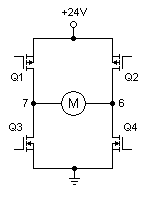
Using N-channel MOSFETs for the upper transistors Q1 and Q2 will not work because the drains have to be pulled up to the 12V rail when they are on, and the gate has to be still more positive than the drain. That's not possible unless another power supply higher than 12V is used for the driver circuit. A more practical solution is to use P-channel MOSFETs for Q1 and Q2 because a P-channel MOSFET turns on when its gate is negative with respect to the drain. This is shown below.

64_1325858919.png


When you want point 7 high and point 6 low, Q1 and Q4 should be turned on by pulling Q1 gate low and Q4 gate high. At that time Q2 gate should be high and Q3 gate low so that these two transistors are in the off condition. When you want point 6 high and point 7 low, exactly the opposite conditions should exist.

I know this still does not answer all your questions, but let's take things step by step. If the above explanation is clear enough, we can proceed to the next step.
 
Last edited:

Re: 10A mosfet h-bridge

Dear Friends
Hi
You should prevent from using the PMOS at h bridges . because , their performance is not good. and their rdson is usually higher that nmos. and you should use just nmos. because their characteristics are same with together . and you will need driver , hside and low side for this , such as ir21xxxx series . and you can not drive a mosfet with 5 volt . ( the maximum out put of a micro controller is about 5 volt) and the mosfet with 15 volt can be at saturation region.
Best Wishes
Goldsmith
 
Re: 10A mosfet h-bridge

@goldsmith: It's true that NMOS transistors are preferable because of their lower rDS(on), but they need either a supply voltage higher than Vdd or a dedicated high-and-low-side driver like the IR211x with a floating power supply. I don't think the OP is ready for such refinements yet at this stage.

For example, his initial choice of transistors is the IRF620 which has a much higher rDS(on) than many common PMOS transistors. I have not commented on that yet because I think it's more important for him to understand the basic principles first. Once we have passed that stage, we can go on to deal with the finer points.
 
Re: 10A mosfet h-bridge

Dear Pjdd
Hi
The IR21xx will produce the float ground with a simple capacitor ( that called bootstrap method).
And what is your mean by " supply voltage higher than Vdd" ?
Respectfully
Goldsmith
 

Re: 10A mosfet h-bridge

The IR21xx will produce the float ground with a simple capacitor ( that called bootstrap method).
Yes, and there are other options too. What I meant was that discussing such techniques will only complicate the discussion and may confuse the OP at this stage.

And what is your mean by " supply voltage higher than Vdd" ?
Sorry, that was bad phrasing on my part. What I meant was that the driver will have to operate from a supply voltage higher than the main Vdd. This is because, if we want the source of the upper NMOS transistor to come up to +24V when it is switched on, the gate will have to be at about +35V above ground.

Whether that +35V comes from a bootstrap circuit or a separate power supply, my point was that it would complicate matters at this stage when we're in the process of discussing the basic principles of bridge operation. Another point is that a bootstrap circuit is not suitable when the transistor has to be kept fully on for an extended period. If the motor has to be kept fully on in one direction, the bootstrap will have to have an almost infinite time constant, which is impossible.
 
Re: 10A mosfet h-bridge

"if we want the source of the upper NMOS transistor to come up to +24V when it is switched on, the gate will have to be at about +35V above ground."
if you don't want use driver ic , yes it is correct and this way called level shifter.
But if you have mosfet driver ic , it is not correct , and your gate voltage will be +15 volt and your source considered zero with bootstrap capacitor.
 
Re: 10A mosfet h-bridge

thanx goldsmith!!!! that was really helpful. i saw a datasheet of mosfet RFG30p06 and the gate to source Vgs(threshold) was -(2 to 4 volts). and there was one more voltage provided which showed Vgs = +/- 20v. which is absolute max. ratings for it at ambient temp. so is it dat i should apply voltage between -4 to -20 v to drive it into saturation ? . but after threshold it will go in active region . and they have not provided any min. voltage required to drive it into saturation. so that i can use it as switch.. plz tell whether i am thinking in right direction.
thanx in advance!!
 
Last edited:

Re: 10A mosfet h-bridge

Dear Friend
Again Hi
That is the threshold voltage . if you want that your mosfet become saturation completely , you should give it , the voltages between 12 volt up to 15 volt.
Best Wishes
Goldsmith
 
Re: 10A mosfet h-bridge

The bootstrap works like a floating voltage and essentially adds on the source voltage just like a battery in series with another battery.
The problem in the high side N mosfet case is that when the mosfet conducts then the source has almost the same voltage as the drain so in order to apply a Vgs of 10 or 15v you either need a voltage that is higher that the voltage applied to the drain or a voltage that is floating so that it can be added on the source.

In the bootstrap method you are essentially charging a capacitor and then connect it between the source and gate, because of the fact that this capacitor is not connected to the ground but on the source the voltage it has adds on the voltage of the source.
For example if you have 12v at the drain and the mosfet conducts then you will have (almost) 12v at the source, when you connect a capacitor that is charged with 12v between the source and gate then the gate voltage will be 12v+12v and the Vgs with be 12v.

In that case I would describe the circuit as having 24v at the gate and a Vgs 0f 12v , I think it would be better if all the voltages on the circuit are measured against the same reference point, if you say that the Vgs is 15v then it makes perfect sense but to say that the gate has 15v if you consider that the source is 0v seems to complicate things.

Alex
 
Re: 10A mosfet h-bridge

okay!! got it .. thanx a lot.. now i just need two ir2113 IC's to drive my mosfet h-bidge. is that it?...just 4 mosfets (rfg30p06) and 2 mosfet drivers ir2113 provided i am using all n-channel mosfets .

---------- Post added at 16:30 ---------- Previous post was at 15:17 ----------

can anyone please give directions for selecting mosfet drivers for mosfet RFG30p06/RFP30p06.
 

Re: 10A mosfet h-bridge

Dear
How much voltage do you need and what is your frequency?
Best lucks
Goldsmith
 

Re: 10A mosfet h-bridge

as stated earlier i am designing a motor driver for 24v and 10A. and as i have selected the mosfet rfg30p06 . it needs 12 to 15 volts to drive it into saturation as advised earlier.
and about frequency.. i think it will depend on the microcontroller i'll use. since the pwm from microcontroller will drive the ckt. but if i use avr then might be 10khz will be my frequency.
 

Re: 10A mosfet h-bridge

well
Why you don't use IRFZ44 ? ok the input current of your mosfet at this frequency is not high . you can use from ir2110 or 1r2113 . the mosfet driver should can work at your frequency and should supply your current . and because , at this frequency , your gate current is not high , IR2110 or ir2113 are good choices.
Best Things
Goldsmith
 

    V

    Points: 2
    Helpful Answer Positive Rating
Status
Not open for further replies.

Similar threads

Part and Inventory Search

Welcome to EDABoard.com

Sponsor

Back
Top