Continue to Site

Welcome to EDAboard.com

Welcome to our site! EDAboard.com is an international Electronics Discussion Forum focused on EDA software, circuits, schematics, books, theory, papers, asic, pld, 8051, DSP, Network, RF, Analog Design, PCB, Service Manuals... and a whole lot more! To participate you need to register. Registration is free. Click here to register now.

how to realize 3.3v to 1.2v(can't use LDO. if DC-DC,then shouldn't use inductor)

Status
Not open for further replies.

fencl

Member level 1
Joined
Jun 17, 2008
Messages
35
Helped
0
Reputation
0
Reaction score
0
Trophy points
1,286
Activity points
1,562
how to realize 3.3v to 1.2v(only can use DC-DC without inductor)

hi,all
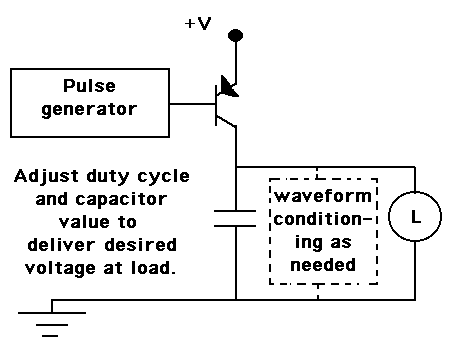
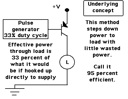
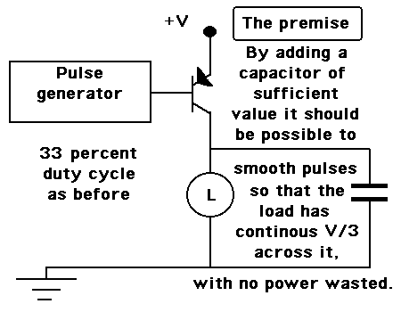
now i need convert 3.3v or 2.5v to 1.2v~1v in cmos0.13um process. if i can't use LDO, only use DC-DC(but without inductor!).how can i do? the ripple need to keep below 50mv.loding up to 30mA .and efficiency > 60~70% is accepted.
Does anyone has relate experience,or some proble way? i need you help, idea, reference papers,or any relate note.

Thanks!
 
Last edited:

Some simple conclusions.

>60% efficiency requires switched mode, if inductors aren't available, switched capacitors are the only option. You have to find out if it's feasible.
 

To expand on what FvM said: 1.2V is 36% of 3.3V. A linear step-down technique using series diodes or a regulator cannot have an efficiency higher than that. That leaves only some form of switching technique.
 

It is feasible to chop the supply into pulses, then feed them to the top of a capacitor. The capacitor then powers the load at a reduced voltage.

The load voltage is determined by adjusting the duty cycle.

Regulation will take a little more work. However if your load is unchanging then you'll achieve a reasonably stable voltage on the load.
 

I was under the impression, that the operation principle of a switched capacitor voltage converter is basically known - or can be retrieved from the internet. To achieve high efficiency, the voltage across the capacitors has to be kept constant, and differences between input, output and capacitor voltages minimal. A 2:1 step down converter refers to a circuit, where two capacitors are charged in series connection and discharged in parallel connection.

It is feasible to chop the supply into pulses, then feed them to the top of a capacitor. The capacitor then powers the load at a reduced voltage.

The load voltage is determined by adjusting the duty cycle.
I'm not sure which exact circuit is suggested by this description, but I doubt, that is able to fulfill the criteria for high efficiency SC voltage conversion. You should particularly consider, that transferring energy to a capacitor without utilizing an inductor burns a part of the energy according to (Vin-Vc)/Vin.
 

By chopping the supply into pulses, little power is wasted.

Add a filter capacitor and we wind up with something that works like a half-wave power supply.

Here's a simplified schematic.

7_1325466719.gif


It works best when the load is an ohmic resistance.

It's sloppy and it will need a lot of tweaking. Ripple voltage is a problem. Nevertheless it satisfies the efficiency requirement.
 

Hi Brad,

It is a nice solution, but are you sure it is more efficient than linear regulation (assuming low power regulator)?

Let us ignore the power needed by the "Pulse Generator". When the PNP transistor is turned on a current charges the capacitor for a short time in each cycle. But between the higher supply V+ and the capacitor terminal there must be a sort of resistance to limit this charging current. A power will be dissipated by this equivalent limiting resistance. I believe, we can find out (by calculation) that the power efficiency will turn out be the same of a linear regulator (if its own power can be neglected).

Kerim
 

I'm not sure which exact circuit is suggested by this description, but I doubt, that is able to fulfill the criteria for high efficiency SC voltage conversion. You should particularly consider, that transferring energy to a capacitor without utilizing an inductor burns a part of the energy according to (Vin-Vc)/Vin.
You're on the right track. Indeed you can't efficiently transfer energy between capacitors unless their voltage is very close together.

If you have two capacitors C1 and C2 with V1 and V2 on them respectively, you will have total energy of E1=1/2(C1*V1^2+C2*V2^2). If you connect them in parallel, they will balance out their voltage to V3=(C1*V1+C2*V2)/(C1+C2), with total energy E1=1/2(C1*V1+C2*V2)^2/(C1+C2). For the condition V1=V2, you get E1 = E2 so no energy is lost. But for any other condition E1 > E2 so you lose energy.

I can't say for certain whether it's possible to meet your specifications with switched capacitor circuits or not.... the calculations for efficiency get complicated for an actual charge pump circuit, but nothing good a spreadsheet wouldn't handle. I can say for certain that a regulated charge pump with arbitrary output can be at least as efficient as a LDO.

Oh, but you will need large external capacitors to make the charge pump work. If your goal is to do this without external components then no, I don't think it's possible.

---------- Post added at 23:17 ---------- Previous post was at 21:21 ----------

Okay, I'm fairly certain now that switched capacitors won't help; their theoretical max efficiency is the same as for linear regulators. I don't believe you'll find a solution to your problem without in inductors. And even then, meeting your specs will be difficult (switch mode DC-DC converters generally don't work efficiently at low output voltages and low output power levels like yours). Is it really unacceptable to require an external inductor, or use an external regulator altogether?
 
Last edited:

As suggested you can use switched capacitor constant gm circuit. Use this current to take the reference voltage, I am not sure about regulation though.
 

It is a nice solution, but are you sure it is more efficient than linear regulation (assuming low power regulator)?

Let us ignore the power needed by the "Pulse Generator". When the PNP transistor is turned on a current charges the capacitor for a short time in each cycle. But between the higher supply V+ and the capacitor terminal there must be a sort of resistance to limit this charging current. A power will be dissipated by this equivalent limiting resistance. I believe, we can find out (by calculation) that the power efficiency will turn out be the same of a linear regulator (if its own power can be neglected).

I follow your reasoning. It adds weight to the view others have expressed, that distributing power from one capacitor to another will not solve the efficiency problem.

My approach started with the idea of switching power to the load. All on. All off. More efficient than the linear method. A slight amount of power is wasted in the transistor/mosfet. I had the idea that this was the only waste in my schematic. It should be no more than is wasted in a conventional switch mode converter.

I admit my method displays a certain amount of "Let's apply a short enough pulse to a large enough capacitor, and see if that gets us in the vicinity of the load voltage."

This post is a follow-up for the sake of exploring possibilities, since we did not expect to find a solution in the linear (voltage drop) method.

Diagram to demonstrate the premise:

82_1325501197.gif


Step 2. Add a capacitor to reduce ripple (smooth out pulses). This diagram is like my schematic in post #7 but with the positions of load and capacitor reversed:

54_1325501197.gif


I suppose this method would be well-known as a working method if it really worked. So there goes my million dollar idea, alas.

What would be excellent is if some offshoot of this concept could work with an LED load. However LED's are not an ohmic resistance, and they instantly **** all spare charge from a capacitor when it's greater than their turn-on threshold. So a resistor still is the easy way (and inefficient way) to limit current through LED's.

However for loads which are an ohmic resistance, I'm surprised if the simple switching method in my schematic can't be used (or else modified) to be more efficient than the linear method.
 
Last edited:

As suggested you can use switched capacitor constant gm circuit. Use this current to take the reference voltage, I am not sure about regulation though.
Would you explain what a constant gm circuit is?

---------- Post added at 07:56 ---------- Previous post was at 07:50 ----------

I follow your reasoning. It adds weight to the view others have expressed, that distributing power from one capacitor to another will not solve the efficiency problem.

My approach started with the idea of switching power to the load. All on. All off. More efficient than the linear method. A slight amount of power is wasted in the transistor/mosfet. I had the idea that this was the only waste in my schematic. It should be no more than is wasted in a conventional switch mode converter.

I admit my method displays a certain amount of "Let's apply a short enough pulse to a large enough capacitor, and see if that gets us in the vicinity of the load voltage."

This post is a follow-up for the sake of exploring possibilities, since we did not expect to find a solution in the linear (voltage drop) method.

Diagram to demonstrate the premise:

82_1325501197.gif


Step 2. Add a capacitor to reduce ripple (smooth out pulses). This diagram is like my schematic in post #7 but with the positions of load and capacitor reversed:

54_1325501197.gif


I suppose this method would be well-known as a working method if it really worked. So there goes my million dollar idea, alas.
This is just like using a LDO but switching it on and off at some duty cycle. It's still a LDO, and it still has the same efficiency limitations, since when conducting the transistor still drops a voltage of Vin-Vout. So no this can't work.
What would be excellent is if some offshoot of this concept could work with an LED load. However LED's are not an ohmic resistance, and they instantly **** all spare charge from a capacitor when it's greater than their turn-on threshold. So a resistor still is the easy way (and inefficient way) to limit current through LED's.

However for loads which are an ohmic resistance, I'm surprised if the simple switching method in my schematic can't be used (or else modified) to be more efficient than the linear method.
I think it boils down to this: in order to transfer energy and change voltage, you need a component whose stored energy does not change when its voltage is changed. The only thing that satisfies that condition is an inductor. So with the exception of certain switched capacitor circuits (voltage inverters/doublers/etc), you need inductors to make efficient DC/DC converters.
 

switched cap cir.JPG
I attached raw image. I guess you got what I said.
 

Attachments

  • switched cap cir.JPG
    switched cap cir.JPG
    19.1 KB · Views: 149

Here only problem is of bigger size of capacitor, and ripple. May be we need cascaded stages to stabilize that.
Another beauty of circuit is, variation is purely depends on capacitor ratios, and hence variation effect can also nulled.
 

Okay, I'm fairly certain now that switched capacitors won't help; their theoretical max efficiency is the same as for linear regulators. I don't believe you'll find a solution to your problem without in inductors. And even then, meeting your specs will be difficult (switch mode DC-DC converters generally don't work efficiently at low output voltages and low output power levels like yours). Is it really unacceptable to require an external inductor, or use an external regulator altogether?

The discussion about the feasibility of switched capacitors has been a theoretical one from my side. I didn't consider technological limits like switch properties at specific supply voltages. I'm also not involved with IC design and not motivated to design a good SC converter. I mainly made some conclusions from the specifications of the original question. As the discussion shows, the basic physic hasn't been understood by all contributors. As KerimF mentioned, the sugegsted pulse charge regulator has exactly the same efficiency as a linear regulator:

η = Vout/Vin

You'll however find examples of energy efficient SC converters in literature, partly using several levels of capacitor parallel/series switching to achieve optimal efficiency for different voltage ratios. As a simple example, you can refer to National LM3350, a fractional 3/2 or 2/3 converter with 90% efficiency.
 
  • Like
Reactions: KerimF

    KerimF

    Points: 2
    Helpful Answer Positive Rating
You'll however find examples of energy efficient SC converters in literature, partly using several levels of capacitor parallel/series switching to achieve optimal efficiency for different voltage ratios. As a simple example, you can refer to National LM3350, a fractional 3/2 or 2/3 converter with 90% efficiency.

I agree with you. A 1:2 switch cap (two in series then in parallel) can be very efficient but it depends on the output voltage. For example, if your desired output voltage is exactly Vdd/2 (1.65 V in this case) the circuit will be nearly 100% efficient. Of course you can't supply any current and maintain Vdd/2 unless your caps are infinite. You will lose efficiency when you regulate it down to 1.2V. Regulation is obtained by controlling the amount of charge you put on the caps when connected to the supply by using a controlled impedance/current source of some sorts. If memory serves, the efficiency has a theoretical upper limit of 1.2V/1.65V = 72%.

You might be able to a 1:3 stepdown plus a pull-up to bring the voltage up. I like that idea so you have to tell me if it works.

The idea of pulsing a current into a capacitor will not work any better than an ideal linear regulator/LDO. Its theoretical max efficiency will be 1.2V/3.3V = 36%. This is because the total charge to the load comes directly from the supply.

When finding the upper limit on efficiency of these charge pumps it is easiest to calculate the amount of charge needed to come from the supply to satisfy the charge going to the load. For example, for a 2:1 that needs to supply "Q" to the load during a period dT, you have two caps in parallel so each cap can supply Q/2 to the load. Therefore, the power supply only needs to furnish Q/2 to each cap when placed in series. The efficiency is (Vdd*Q/2/dT)/(Vout*Q/dT) where dT is the period. If Vout = Vdd/2 the efficiency is 100%.
 
Last edited:
  • Like
Reactions: FvM

    FvM

    Points: 2
    Helpful Answer Positive Rating
Hi,

To me, charging a capacitor with (Q) during a time (t) means the capacitor should be supplied by an average current of (Q/t). Perhaps I am wrong, I think, the trick of the relative high efficiency sometimes we hear of is that the power dissipated due to this pulsed current occurs in the regulated voltage source itself, as (Vin-Vout)*di for example, during the charge.
Naturally (as far as I know), there is no real (quasi ideal) 'current' source without using inductors. So anytime there is a current flow coming from a 'voltage' source, we need to look how it is limited (ideally the current should be infinite). This leads us to where the power loss occurs.

I look forward to see how far I am wrong :)

Kerim
 

You'll however find examples of energy efficient SC converters in literature, partly using several levels of capacitor parallel/series switching to achieve optimal efficiency for different voltage ratios. As a simple example, you can refer to National LM3350, a fractional 3/2 or 2/3 converter with 90% efficiency.
Correct, and circuits like are efficient because the voltage of each capacitor in the circuit is equal and pretty much constant. So with additional capacitors and stages, it's you can get any Vout/Vin ratio with good efficiency. But 3.3V to 1.2V is a pretty inconvenient ratio (11/4), so you'd need a ton of stages and switches. Maybe using a 1/3 divider could work as well.

But I had the feeling that the OP was asking this because he didn't want large external components, which means that SC circuits would probably be unacceptable anyways. At the very least the total size of the capacitors probably wouldn't be smaller than the single inductor of a buck converter.
 

To me, charging a capacitor with (Q) during a time (t) means the capacitor should be supplied by an average current of (Q/t).
Kerim

Efficiency degrades from the loss of charge, If there is constant path from Supply to ground, your circuit is lossy. In case of SC circuits charge is never lost other than load. few SC based circuits are already exampled by ROBG and FVM. These SC circuits gives efficiency more than 90% ( <10% across switches).
Example, in linear regulators (LDO) there is a constant path from supply to ground even if there is no load while in Buck regulator efficiency is more than 70%, because charge is coming from LC filter ( when supply is off).

Now coming the main post, LDO is best architecture for the required voltage range, should be used. I always prefer Buck/boost architecture though. but trade off is efficiency vs area. Most of the time Switched capacitor circuits are best suited due to their simplicity of the design.
 

I couldn't get what "loss of charge" could mean. What came to mind is an AC transmission line, charges are not lost only their energy.
 

Status
Not open for further replies.

Similar threads

Part and Inventory Search

Welcome to EDABoard.com

Sponsor

Back
Top