Design of resistance values for Opamp for +/- input voltage range amplification and conversion to linear output ranges –
The automation and control system kind of applications consists of sensor interfacing with micro-controller. In many cases like PH sensor output or temperature sensor used for negative and positive temperatures gives the sensing signal or voltages in +/- range.
The common voltage for sampling and detection of the micro-controller has range for only positive voltages for the detection i.e. 0 to let say 5v of the range. In such a situation it is necessary to have the negative voltage need to converted in the positive voltage for sampling and detection. Aslo corresponding range for the measurement need to be maintained for such a application. This article highlights a simple and powerful method using Opamp and its design consideration.
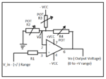
Consider the circuit attached –
In this circuit the Opamp is used non-inverting amplification mode Because this will not have very less loading effect on the input
Let consider
V_in_neg is negative input voltage and V_in_pos is positive input voltage ( range for input voltages)
And one is expected to get the range of output voltage of Vo_neg and Vo_pos
Now one can write the KCL equation at the node –VA will give you following things
(Va -Vo_pos) /R4 + (Va- 0)/R2 + (Va – (-V))/R3 =0 ……………………….equation-1
Now Va is nothing but V_in_pos based on the concept of virtual ground
Thus equation 1 becomes –
(V_in_pos -Vo_pos) /R4 + (V_in_pos - 0)/R2 + (V_in_pos – (-V))/R3 =0 ……………………….equation-2
And similarly for negative range voltage also-
(Va - Vo_neg) /R4 + (Va- 0)/R2 + (Va – (-V))/R3 =0 0 ……………………….equation-3
Now Va is nothing but V_in_neg based on the concept of virtual ground
(V_in_neg - Vo_neg) /R4 + (V_in_neg - 0)/R2 + (V_in_neg – (-V))/R3 =0 0 ……………………….equation-4
If we still resolve the equation 2 and 4 then one can get –
Vo_pos = V_in_pos ( 1+ R4*((1/R2 )+ (1/R3)) ) + V * R4/r3 0 ……………………….equation-5
Vo_neg = V_in_neg ( 1+ R4*((1/R2 )+ (1/R3)) ) + V * R4/r3 0 ……………………….equation-5
These equations are
Y= mx + c form …..equation linear lines…
If one fixes the value of R4 – feedback resistors as a constant then one can obtain the values of R2 and R3 by solving above equations.
And hence one will able to convert the +/- range of input voltage ranage to postive output range for interfacing
The purpose of adding R1 is increase the input impedance one can remove that too…
I hope this article may help to you.
Good Luck

The automation and control system kind of applications consists of sensor interfacing with micro-controller. In many cases like PH sensor output or temperature sensor used for negative and positive temperatures gives the sensing signal or voltages in +/- range.
The common voltage for sampling and detection of the micro-controller has range for only positive voltages for the detection i.e. 0 to let say 5v of the range. In such a situation it is necessary to have the negative voltage need to converted in the positive voltage for sampling and detection. Aslo corresponding range for the measurement need to be maintained for such a application. This article highlights a simple and powerful method using Opamp and its design consideration.
Consider the circuit attached –
In this circuit the Opamp is used non-inverting amplification mode Because this will not have very less loading effect on the input
Let consider
V_in_neg is negative input voltage and V_in_pos is positive input voltage ( range for input voltages)
And one is expected to get the range of output voltage of Vo_neg and Vo_pos
Now one can write the KCL equation at the node –VA will give you following things
(Va -Vo_pos) /R4 + (Va- 0)/R2 + (Va – (-V))/R3 =0 ……………………….equation-1
Now Va is nothing but V_in_pos based on the concept of virtual ground
Thus equation 1 becomes –
(V_in_pos -Vo_pos) /R4 + (V_in_pos - 0)/R2 + (V_in_pos – (-V))/R3 =0 ……………………….equation-2
And similarly for negative range voltage also-
(Va - Vo_neg) /R4 + (Va- 0)/R2 + (Va – (-V))/R3 =0 0 ……………………….equation-3
Now Va is nothing but V_in_neg based on the concept of virtual ground
(V_in_neg - Vo_neg) /R4 + (V_in_neg - 0)/R2 + (V_in_neg – (-V))/R3 =0 0 ……………………….equation-4
If we still resolve the equation 2 and 4 then one can get –
Vo_pos = V_in_pos ( 1+ R4*((1/R2 )+ (1/R3)) ) + V * R4/r3 0 ……………………….equation-5
Vo_neg = V_in_neg ( 1+ R4*((1/R2 )+ (1/R3)) ) + V * R4/r3 0 ……………………….equation-5
These equations are
Y= mx + c form …..equation linear lines…
If one fixes the value of R4 – feedback resistors as a constant then one can obtain the values of R2 and R3 by solving above equations.
And hence one will able to convert the +/- range of input voltage ranage to postive output range for interfacing
The purpose of adding R1 is increase the input impedance one can remove that too…
I hope this article may help to you.
Good Luck