By Bill Schweber
As the use of LEDs for area lighting has grown dramatically, with both the use of LED-based replacement bulbs as well as LED-based fixtures for new construction (called luminaires in the trade), the issue of dimming these LEDs becomes more critical. LEDs require a very different technique for dimming than the conventional legacy incandescent bulb. The dimming technique differs greatly if the LED is being used in a retrofit installation that already has an incandescent dimmer, versus a new installation with a dimmer circuit designed specifically and only for LEDs.
How are incandescent bulbs dimmed?
The simplistic and historical way to dim incandescent bulbs powered from the standard AC line was to reduce the voltage. This works but has several major drawbacks:
as the voltage is decreased from its design value, the sunlight-like color and appearance of the incandescent filament gets yellow and then reddish-brown, which is unattractive and harsh;
the rheostat (a variable resistor) which cuts the voltage is actually wasting power, which is costly and inefficient;
the rheostat dissipation also represents considerable heat, which is a hazard in addition to the inefficiency, and so it must be cooled in a separate box from the wall switch and control.
As a result, dimming of line-powered incandescent bulbs was impractical in homes for many years, although it was done using rheostats for applications such as theater lighting.
How are incandescent bulbs now dimmed?
Due to the development of the TRIAC – TRIode for Alternating Current – a low-cost, easily controlled, solid-state switch for AC current, dimming became affordable, reliable, and efficient. Dimmers which replace a standard wall switch in the same outlet box sell for under $10, with millions of these are in regular use.
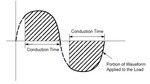
Instead of reducing the line voltage to the bulb, the TRIAC is controlled by an internally generated DC voltage to “turn on” and pass the AC line at differing points in the AC-line phase, but always including the maximum line voltage, Figure 1. In effect, the AC line is chopped at a variable phase angle, yet always ensures that maximum line voltage is applied to the bulb each cycle. As a result, the bulb is able to glow at its maximum value, but for shorter periods of time. The thermal mass of the filament integrates the phase-controlled, chopped voltage to yield a brightness which is proportional to RMS applied voltage and thus power.

Fig 1: In a standard TRIAC-based dimmer for incandescent bulbs, the sinusoidal waveform is turned on/off at differing phase angles to adjust brightness, ensuring full voltage applied with each half-cycle but with overall reduced RMS power. (Source: ON Semiconductor)
How does LED dimming compare to incandescent dimming?
LEDs are current-sourced light sources. The obvious way to dim the LED is analogous to using a rheostat, except that instead of decreasing the AC line voltage, the system reduces the DC-current drive to the LED. However, for applications such as area lighting, the results are unacceptable, as the color output of the LED changes, and performance is inconsistent. Instead, a controllable current source is used.
The much-better way to dim an LED is to pulse-width modulate the current, driving the LED current to its maximum and cutting it off completely, with an adjustable duty cycle to control the timing and thus range, Figure 2. Unlike incandescent bulbs which have thermal mass and so don’t flicker as their power goes through the on/off cycles of the AC waveform, LEDs have very fast response time and will actually turn on and off in synchronization with the drive current. For this reason, most LED-dimming ICs implement the PWM at a relatively high rate of at least 200 Hz, so the eye does not see annoying flicker. Some LED dimmers also do not cut the drive to zero, but maintain a modest “idle” current of about 10% of maximum to reduce some latent flicker and other effects.
There are other issues associated dimming LEDs in AC-powered situations. Regulatory mandates require that loads present a high power factor (PF) to the line, with specific PF number a function of the load wattage. This is not an issue for incandescent bulbs, which inherently have a PF of unity (1) due to their resistive nature. However, the LED drive circuitry which is being driven by the AC line is not resistive, and so it must implement power factor correction (PFC) to meet the regulatory requirements.
What about LED dimming where TRIAC dimmers are in use?
For LED-based luminaires and lighting systems which are increasingly used in new or upgrade installations, this PWM-controlled dimming current is all that the LED needs to see. This requirement is readily met by ICs which are specially designed for the situation. However, the millions of TRIAC-based dimmers are not going to be removed and replaced with “native” LED dimmers, while resident expects to put an LED-based bulb into the socket in place of the incandescent, and be able to dim it using the same TRIAC dimmer that is already in place.
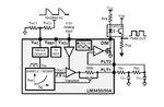
To solve this problem, LED bulb designers have added special circuitry to the AC/DC drive-conversion built into the base of these replacement LEDs. ICs such as the Texas Instruments LM3450 provides required PFC along with LED dimming control, Figure 2. This LED driver interprets phase-controlled dimming waveform from the TRIAC wall dimmer and translates this into a corresponding pulse width modulated waveform.

Fig 2: To translate the phase-controlled brightness waveform from a TRIAC-based dimmer, the LM3450 IC uses a rectified version of the AC line as its input and decodes this into a PWM-current waveform for the LED; it also dynamically adjusts operating parameters to implement PFC so the circuit appears to have a powerfactor close to unity as seen by AC line. (Source: Texas Instruments)
It does this by detects the dimming angle of a rectified AC current, decodes the dimming angle, filtering it, and “remapping” the output DC current drive into a 500-Hz pulse-modulated waveform which can properly dim an LED. Bulbs which have this internal circuit are marked as “dimmable” so retail purchasers know they can be used in existing dimmer installations.
References
Texas Instruments SNVA605, “Dimming Techniques for Switched-Mode LED Drivers”
ON Semiconductor AND8448/D, “Configuring the NCL30000 for TRIAC Dimming”
As the use of LEDs for area lighting has grown dramatically, with both the use of LED-based replacement bulbs as well as LED-based fixtures for new construction (called luminaires in the trade), the issue of dimming these LEDs becomes more critical. LEDs require a very different technique for dimming than the conventional legacy incandescent bulb. The dimming technique differs greatly if the LED is being used in a retrofit installation that already has an incandescent dimmer, versus a new installation with a dimmer circuit designed specifically and only for LEDs.
How are incandescent bulbs dimmed?
The simplistic and historical way to dim incandescent bulbs powered from the standard AC line was to reduce the voltage. This works but has several major drawbacks:
as the voltage is decreased from its design value, the sunlight-like color and appearance of the incandescent filament gets yellow and then reddish-brown, which is unattractive and harsh;
the rheostat (a variable resistor) which cuts the voltage is actually wasting power, which is costly and inefficient;
the rheostat dissipation also represents considerable heat, which is a hazard in addition to the inefficiency, and so it must be cooled in a separate box from the wall switch and control.
As a result, dimming of line-powered incandescent bulbs was impractical in homes for many years, although it was done using rheostats for applications such as theater lighting.
How are incandescent bulbs now dimmed?
Due to the development of the TRIAC – TRIode for Alternating Current – a low-cost, easily controlled, solid-state switch for AC current, dimming became affordable, reliable, and efficient. Dimmers which replace a standard wall switch in the same outlet box sell for under $10, with millions of these are in regular use.
Instead of reducing the line voltage to the bulb, the TRIAC is controlled by an internally generated DC voltage to “turn on” and pass the AC line at differing points in the AC-line phase, but always including the maximum line voltage, Figure 1. In effect, the AC line is chopped at a variable phase angle, yet always ensures that maximum line voltage is applied to the bulb each cycle. As a result, the bulb is able to glow at its maximum value, but for shorter periods of time. The thermal mass of the filament integrates the phase-controlled, chopped voltage to yield a brightness which is proportional to RMS applied voltage and thus power.
Fig 1: In a standard TRIAC-based dimmer for incandescent bulbs, the sinusoidal waveform is turned on/off at differing phase angles to adjust brightness, ensuring full voltage applied with each half-cycle but with overall reduced RMS power. (Source: ON Semiconductor)
How does LED dimming compare to incandescent dimming?
LEDs are current-sourced light sources. The obvious way to dim the LED is analogous to using a rheostat, except that instead of decreasing the AC line voltage, the system reduces the DC-current drive to the LED. However, for applications such as area lighting, the results are unacceptable, as the color output of the LED changes, and performance is inconsistent. Instead, a controllable current source is used.
The much-better way to dim an LED is to pulse-width modulate the current, driving the LED current to its maximum and cutting it off completely, with an adjustable duty cycle to control the timing and thus range, Figure 2. Unlike incandescent bulbs which have thermal mass and so don’t flicker as their power goes through the on/off cycles of the AC waveform, LEDs have very fast response time and will actually turn on and off in synchronization with the drive current. For this reason, most LED-dimming ICs implement the PWM at a relatively high rate of at least 200 Hz, so the eye does not see annoying flicker. Some LED dimmers also do not cut the drive to zero, but maintain a modest “idle” current of about 10% of maximum to reduce some latent flicker and other effects.
There are other issues associated dimming LEDs in AC-powered situations. Regulatory mandates require that loads present a high power factor (PF) to the line, with specific PF number a function of the load wattage. This is not an issue for incandescent bulbs, which inherently have a PF of unity (1) due to their resistive nature. However, the LED drive circuitry which is being driven by the AC line is not resistive, and so it must implement power factor correction (PFC) to meet the regulatory requirements.
What about LED dimming where TRIAC dimmers are in use?
For LED-based luminaires and lighting systems which are increasingly used in new or upgrade installations, this PWM-controlled dimming current is all that the LED needs to see. This requirement is readily met by ICs which are specially designed for the situation. However, the millions of TRIAC-based dimmers are not going to be removed and replaced with “native” LED dimmers, while resident expects to put an LED-based bulb into the socket in place of the incandescent, and be able to dim it using the same TRIAC dimmer that is already in place.
To solve this problem, LED bulb designers have added special circuitry to the AC/DC drive-conversion built into the base of these replacement LEDs. ICs such as the Texas Instruments LM3450 provides required PFC along with LED dimming control, Figure 2. This LED driver interprets phase-controlled dimming waveform from the TRIAC wall dimmer and translates this into a corresponding pulse width modulated waveform.
Fig 2: To translate the phase-controlled brightness waveform from a TRIAC-based dimmer, the LM3450 IC uses a rectified version of the AC line as its input and decodes this into a PWM-current waveform for the LED; it also dynamically adjusts operating parameters to implement PFC so the circuit appears to have a powerfactor close to unity as seen by AC line. (Source: Texas Instruments)
It does this by detects the dimming angle of a rectified AC current, decodes the dimming angle, filtering it, and “remapping” the output DC current drive into a 500-Hz pulse-modulated waveform which can properly dim an LED. Bulbs which have this internal circuit are marked as “dimmable” so retail purchasers know they can be used in existing dimmer installations.
References
Texas Instruments SNVA605, “Dimming Techniques for Switched-Mode LED Drivers”
ON Semiconductor AND8448/D, “Configuring the NCL30000 for TRIAC Dimming”