Continue to Site

Welcome to EDAboard.com

Welcome to our site! EDAboard.com is an international Electronics Discussion Forum focused on EDA software, circuits, schematics, books, theory, papers, asic, pld, 8051, DSP, Network, RF, Analog Design, PCB, Service Manuals... and a whole lot more! To participate you need to register. Registration is free. Click here to register now.

How to use GT60N321 IGBT to control 3 phase Induction motor?

Dhruv1253

Newbie
Joined
May 3, 2024
Messages
4
Helped
0
Reputation
0
Reaction score
0
Trophy points
1
Activity points
37
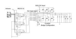
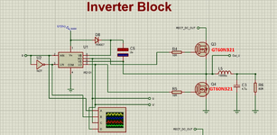
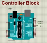
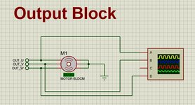
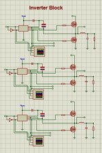
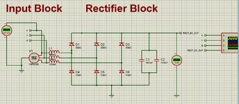
Hello Everyone..! I am using GT60N321 Toshiba make IGBT to control 3 phase motor. I have used 6 IGBTs in full bridge configuration. Gate pulses are given from IR2101 IC (10Volts Output) which in turn driven from Arduino mega. 550Volts DC to be connected at collector terminal of IGBTs. We were expecting 400V AC output. But we are not getting full output as expected. Output is limited to 22V. Please suggest what could have gone wrong? Suggestion with regard to Schematic, Circuit diagram, Code will be appreciated. My circuit diagram for your reference has been attached.
 

Attachments

  • Query1.png
    Query1.png
    78.3 KB · Views: 36
I've not worked with IGBT type but if their bias is like ordinary transistors you need greater than supply_V at bias to turn on N-devices. Likewise P-devices in symmetry because to shut them off they need bias voltage identical to supply_V. Since you speak of pulses it suggests you wish to switch them entirely Off and entirely On.

You state your supply 550V to IGBT collector which implies you have N-devices. Imagine a high-side N-device starts to turn On. So as soon as you turn On that high-side N-device, 550V appears on its lower (emitter) leg. All of a sudden your gate bias voltage must be higher than whatever appears on its lower leg. Therefore your bias V must be greater than 550v!

You might obtain a supplemental level from the supply itself (via resistor) but a bootstrap circuit is probably needed to raise your gate-drive even higher.
 
Hi,

A lot of informations missing:
WHAT do you measure and HOW?
What is the input signal to the gate_drivers?

The schematic is so low in resolution one can not detect any details.

But I guess there´s something wrong with gate driver wiring. I see just 6 signals to the drivers, but you need at least 10:
* 1 x POWER_GND
* 3 x LO
* 3 x VS
* 3 x HO

Where is this schematic from? Hopefully from a semiconductor manufacturer´s application note (and not some random unreliable internet source)

And as always: swtiching power circuits are ciritical in PCB layout design. Be sure to follow all semiconductor manufacturers recommendations.
You can´t just do some connections (without concept) and hope it will work.

Klaus
 
Guys, please consider the attached images of circuit diagram for your reference. we tried to simulate in proteus, in which motor runs. but physically we observed some issues with inverter module. Its output is not as expected. Rectifier is working fine. Rectifier output is 550 V. which is given to collector of high side IGBTs.
Expected output at Inverter output side is 400V AC. but we are getting only 10-20Volts output.

while handling single IGBT, issue we found with GT60N321 IGBTs are:-
1) When we give 10V Gate, 24V Collector, then we get only 12-13V output at Emitter
2) When we give 19V Gate, 24V Collector, then we get 23V output at Emitter
but
3) When we give 19V Gate, 50V Collector, then still we get 27V output at Emitter. which should not have happened. We expect 48V approx output at emitter.

Output are being measured using multimeter. In practical we are giving 6 signals from Arduino to 6 IGBTs.
Arduino code has been attached for your reference.
 

Attachments

  • INVERTER_DIAGRAM.png
    INVERTER_DIAGRAM.png
    1.2 MB · Views: 22
  • WhatsApp Image 2024-05-03 at 13.44.05 (1).jpeg
    WhatsApp Image 2024-05-03 at 13.44.05 (1).jpeg
    62.7 KB · Views: 21
  • WhatsApp Image 2024-05-03 at 13.44.05.jpeg
    WhatsApp Image 2024-05-03 at 13.44.05.jpeg
    71.3 KB · Views: 19
  • WhatsApp Image 2024-05-03 at 13.44.04 (1).jpeg
    WhatsApp Image 2024-05-03 at 13.44.04 (1).jpeg
    54.3 KB · Views: 18
  • WhatsApp Image 2024-05-03 at 13.44.04.jpeg
    WhatsApp Image 2024-05-03 at 13.44.04.jpeg
    154.6 KB · Views: 20
  • Declaring Frequency.txt
    2.8 KB · Views: 13
Sounds like you don't understand operation of bootstrap gate drivers and don't test it in the right way.
 
Hi,

what´s this? Totally different schematics? I guess you want to fool us.

Klaus
 
Hi,

what´s this? Totally different schematics? I guess you want to fool us.

Klaus
No Klaus. With all due respect, I am working on this circuit day in and out. I want to run 3 phase AC motor using Arduino. hence the circuit
 
At least driver terminals VS aren't connected in post #1 schematic. Bootstrap doesn't work without this connection.
now we have updated the circuit. please help me to understand bootstrap drivers
 
please help me to understand bootstrap drivers
I wonder why semiconductor manufacturers invest time and effort to write datasheets and application notes.
They explain everything in detail, give example schematics, show formulae, give PCB layout recommendations... while people just ignore them.
These documents are way more detailed than a forum post can be.
And your question does not ask for a detail .. that needs a human to focus on it.

From my experience (and a lot of my knowledge comes from semiconductor manufacturer documents) .. I read the documents, follow their recommendations and in 99% it works like expected. The remaining 1% is a mixture of my own mistakes and mistakes/unclear description. Usually I don´t need a simulation nor a test circuit.

Toshiba, TI, Rohm, Onsemi, Infineon ... provide documents on the first page of an internet search about "bootstrap circuit". Even Wikipeda has an article...
And there are videos.


No one was born with all wisdom. And surely I´m not an exception. In my early days as an electronics designer there was no internet. We had to go to the library .. and I had to hope that in my small town there was a single book that included what I was looking for. Now there is the internet, with billions of documents available in seconds. Free to use...


Klaus
 

LaTeX Commands Quick-Menu:

Similar threads

Part and Inventory Search

Welcome to EDABoard.com

Sponsor

Back
Top