Continue to Site

Welcome to EDAboard.com

Welcome to our site! EDAboard.com is an international Electronics Discussion Forum focused on EDA software, circuits, schematics, books, theory, papers, asic, pld, 8051, DSP, Network, RF, Analog Design, PCB, Service Manuals... and a whole lot more! To participate you need to register. Registration is free. Click here to register now.

zero Crossing circuit with a minimum of external components

Status
Not open for further replies.

azadfalah

Full Member level 2
Joined
Aug 13, 2016
Messages
145
Helped
1
Reputation
2
Reaction score
2
Trophy points
1,298
Activity points
2,423
hi friends

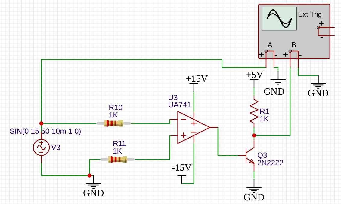
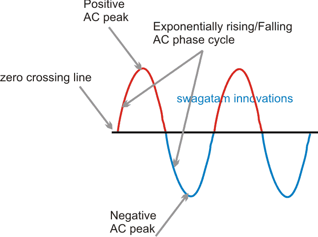
In a project I need to detect zero Crossing in main input
* It is better to do this with the least parts
* To measure the main voltage, the ground and Main neutral are connected in some way ( So the circuit can not be isolated )
*No part of the board is not in contact with the user's body and there is at least 5 mm of plastic cover ( Do not focus on isolation )

I have seen the same circuit before on another device that has worked without problems for years but I do not feel good about it
If I use this circuit. What are the significant risks?


Zero Cross.PNG


Thanks a lot
 

Presumed you are building the circuit with safe insulation, e.g. regarding clearance/creepance distances and resistor voltage rating. Circuit function will depend on relation of circuit GND to mains. How is the circuit power supplied? Are circuit parts exposed to the operator? If the circuit is plug connected, mains hot and neutral can be interchanged.
 
Hi,

* It is better to do this with the least parts
Yes, nobody looks for a circuit with as many as possible parts. Every body looks for low part count.

But often this is not possible, because there are requirements.
You are the developer, thus you need to know the requirements.
Requiremnts are:
* safety. Maybe isolate, maybe not
* timing. The more precise the timing you need, the more complicated the circuit.
* clean levels. If you can live with noisy, slow rising, slow falling, ringing bad voltage levels, then the circuit may become simple
* protection. Against ESD, against other overvoltage or wrong wiring.... Often the microcontroller manufacturer specifies, that the internal protection diodes must not be used for "normal operation" - like in your circuit above.
* reliable operation. The more reliable, the more complicated. Your circuit above is likely to work when the microcontroller is battery powered, maybe even when you use a low frequency mains transformer based power supply. But maybe it does not work with a switch mode power supply, when there is high frequency coupled form primary to secondary side.

So the circuit above may work or not. It may (over long time) kill the microcontroller or not.
It may work with the one power supply but not with the other. It may work with one microcontroller (even if same partnumber) but not with the other, it may work on low humidity but not on high humidity. It may work when the device is on a table, but not when one holds it in the hands.

"Low part count design" often is "bad design".
You are free to do what you want.

Klaus
 
Thanks for your reply friends

How is the circuit power supplied?
Are circuit parts exposed to the operator?
If the circuit is plug connected, mains hot and neutral can be interchanged.

Through a 24 volt DC power supply
Not . The parts are inside the box
i add 200Kohm Series Resistor with hot line and neutral and change PD2 pin Resistor to 2Mohm so there is no problem if the inputs change


Yes, nobody looks for a circuit with as many as possible parts. Every body looks for low part count.

But often this is not possible, because there are requirements.
You are the developer, thus you need to know the requirements.
Requiremnts are:
* safety. Maybe isolate, maybe not
* timing. The more precise the timing you need, the more complicated the circuit.
* clean levels. If you can live with noisy, slow rising, slow falling, ringing bad voltage levels, then the circuit may become simple
* protection. Against ESD, against other overvoltage or wrong wiring.... Often the microcontroller manufacturer specifies, that the internal protection diodes must not be used for "normal operation" - like in your circuit above.
* reliable operation. The more reliable, the more complicated. Your circuit above is likely to work when the microcontroller is battery powered, maybe even when you use a low frequency mains transformer based power supply. But maybe it does not work with a switch mode power supply, when there is high frequency coupled form primary to secondary side.

So the circuit above may work or not. It may (over long time) kill the microcontroller or not.
It may work with the one power supply but not with the other. It may work with one microcontroller (even if same partnumber) but not with the other, it may work on low humidity but not on high humidity. It may work when the device is on a table, but not when one holds it in the hands.

"Low part count design" often is "bad design".
You are free to do what you want.

Klaus

Thank you for your answer that's why I don't feel good about this circuit , But this circuit is seen in a device with CE standard
Is the schematic below better?
1617120279256.png
 

Hi,

important question: is there any possibility that HOT and NEUTRAL may be swapped?
If yes: Ask yourself: Does this cause any safety problem? Calculate possible currents and voltages.

Your circuit has only mains connection? no other connetion to outside world? (USB, RS232, display, battery, any metal item, pushbuttons, potentiometer, LEDs, programming connector..)

Your circuit:
Please read datasheet of microcontroller about "absolute maximum input voltage" at the according pin.
I doubt a 1N4148 can satisfy this. (read 1N4148 datasheet)
In doubt I recommend to use schottky diodes instead. Like BAT54S.

I don´t recommend 1N4007 in sereis with a 4V3 zener on a 5V supply. This is just on the edge. Low supply voltage makes the node float in a limited range. Too high input voltage may cause the zener to burn. Do worst case calculations (highest power supply voltage, lowest 4007 forward voltage, lowest zener reverse voltage.. take care about tolerance, aging drift, temperature drift )

A 100R instead of the 1N4007 makes more sense...

Still any coupled noise may cause multiple ZC transitions. Be sure this causes no problems. Maybe you need to adjust software on this.

A switch mode power supply causes noise. Use a scope to get a clue about frequency and magnitude.
Don´t be surprised by more than 50V AC at secondary w.r.t. earth ground.

Klaus
 
Your circuit has only mains connection? no other connetion to outside world? (USB, RS232, display, battery, any metal item, pushbuttons, potentiometer, LEDs, programming connector..)

Hi and thank you for your answer
Yes, the LEDs are on the under of the plastic cover min 5mm plastic to LED lead
there is also a switch with plastic cover with a thickness of 10 mm

do you think this schematic is better than the previous method?
1617123985658.png
 

Hi,

Now you are at 10 parts. Still suffers from problems when noise is introduced. No differential signaling, no filters, no clean switching.
There is a good chance that it will work.
But still not what I call a good solution. But I always want high quality.
No need for you do the same.

May I ask why you don't use clean differential signaling and feed the microcontrollers internal analog comparator with it?

Klaus


Some possibilities....


Regards, Dana.
 
Status
Not open for further replies.

Similar threads

Part and Inventory Search

Welcome to EDABoard.com

Sponsor

Back
Top