Continue to Site

Welcome to EDAboard.com

Welcome to our site! EDAboard.com is an international Electronics Discussion Forum focused on EDA software, circuits, schematics, books, theory, papers, asic, pld, 8051, DSP, Network, RF, Analog Design, PCB, Service Manuals... and a whole lot more! To participate you need to register. Registration is free. Click here to register now.

Why Specific patern of PWM appear as AC signal to load?

Status
Not open for further replies.

umery2k75

Advanced Member level 1
Joined
Apr 19, 2006
Messages
434
Helped
41
Reputation
80
Reaction score
15
Trophy points
1,298
Location
Pakistan
Activity points
5,748
magic sine pwm

In every article,I see regarding Sine wave Inverters, UPS.What they basically all do is to do variation of duty cycle in the PWM signal to provide a DC voltage across the load in a specific pattern, that appears to the load as an AC signal!
But why? Why it happens, how come the complex switching waveform appear as AC wave after passing through filter.Is this because I used Sine wave as a reference in generating PWM.If this is so, then what if I used an audio song as a reference signal beside Sine wave. Take an inverter of 12VDC to 220VAC. Will I be getting a song where it's Peak to Peak is within 622.16V. Vrms=220V, so Vpp = 2*1.414*220=622.16V. Isn't that all Modulation and Demodulation?

In terms of communication I can understand, low frequency like 50Hz can be modulated with a FM frequency and then restore back by removing the carrier and getting back the desired signal of interest. I am trying reading more about this thing from the internet, because I don't have books on these topics.

I am writing these points, they are useful insight.

1)In square wave inverters, maximum output voltage is achievable.
2)However, there is no control in harmonics and output voltage magnitude, that is the harmonics are always at 3,5,7,etc times the fundamental frequency.
3)Hence the cut-off frequency of the low pass filter is some what fixed. The filter size is dictated by VA ratings of the inverter.
4)To reduce filter size, the PWM switching schemce can be utilized.
5)In this techinque, the harmonics are pushed to higher frequencies. Thus the cut-off frequency of filter is increased. Hence filter components(i.e L & C ) sizes are reduced.
6)The trade off this flexibility is complexity in the switching waveforms.
 

igbt + h-bridge + animation

It seems to me, that you are thinking too complicated regarding PWM operation. As you mention, PWM means to generate a DC voltage by variation of duty cycle. I guess that's obvious. The DC voltage is simply the average of the switched output voltage respectively the voltage seen after a low-pass.

Now, if you vary a DC voltage in time, you get an AC voltage, not specicific to PWM at all. When you model a PWM system, you can replace the modulator and switched output stage by a linear amplifier in a time continuous equivalent circuit.

The sine modulation used in many PWM applications hasn't to do with PWM. It's an input signal, it could be processed by a linear system as well. Of course you need a PWM or a linear amplifier to build a sine inverter. And the latter would have a bad efficiency, but that doesn't matter for a model system.

This consideration doesn't answer all detail questions related to PWM, but it gives a clearer view on it's basic behaviour.
 

    thannara123

    Points: 2
    Helpful Answer Positive Rating
generation of overlapping carrier pwm

PWM means to generate a DC voltage by variation of duty cycle.

This is true PWM does the averaging, if I want to generate Pure Sine wave at the output. I alone I cannot think of just RMS voltage of Sine wave.

Modified Sine Wave RMS= Pure Sine Wave RMS

Both Pure Sine wave inverter and modified sine wave inverter makes use of PWM and the interesting thing is that their RMS voltage are same.I want to end up with Sine Wave Output.

The difference between Modified Sine Wave Inverter and Pure Sine Wave Inverter lies in the their wave shape.With the specific PWM pattern I can end up with Pure Sine Wave output or Square Wave Output with Same RMS.Because PWM can tell me how much average voltage I'm getting, but PWM cannot tell me what kind of wave shape I'm getting.
 

filter pwm load


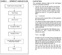
I am using PIC16F73 MCU to drive the H-bridge without taking any feed back.This page is from PICREF-1 about the H-brige drive pattern.

I also try to create the formula, based on the logic that I will have a sine table with VRMS voltage * Sine(angle)

Then I did this:

For First Half Wave with 32 steps
I made a table with these values.

N=1 to 32, theta=1 to 90 deg

Vref(N)=Voltage_RMS*Sin(theta)

BY MICROCHIP

The table is generated from the following equation
with k = 0.... N/2 - 1 and N = the number of
samples per cycle.
Example: For the Vp of the previous example and
N = 64 samples per cycle, this yields the following
table entries. Note that only 32 entries are generated
as the negative-going halfwave may be generated
from the negative of the first 32.
Vref = 0, 25, 50, 74, 98, 120, 142, 162, 180, 197,
212, 225, 235, 244, 250, 254, 255, 254, 250, 244,
235, 225, 212, 197, 180, 162, 142, 120, 98, 74, 50,
25.

Now there are 2 formula

Vref=Vp*Sin(2*pi*k/N) By MICROCHIP
Vref=Vrms*(Sin*angle) By ME

Which forumla is better, on what basis should I compare the two? I just don't want to use Microchip look up table, because I don't have Vp calculated. I cannot calculate Vp because in order to calculate Vp, I must know the A/D voltage gain. But I'm not using A/D for sampling the output, so I don't know what gain value I used. So I cannot calculate Vp, this implies I cannot make Vref. Another thing is that Microchip Vref table has A/D output gain of 1.5 involve in this table. If I use this table, I don't know what effect I will get on my H-bridge and on to my load side.

How MICROCHIP created that formula Vref=Vp*Sin(2*pi*k/N) and what is the logic of this equation?
 

pwm ac

Usually a sine table is scaled to utilize the respective numeric format. The microchip table (two quadrants) uses unsigned int8 (maximum is 255). The modulator gain, in other words the sine amplitude generated by the pwm can be adjusted by either scaling the sine or the triangle function afterwards.

Obviously, without a feedback, you get an output voltage relative to the DC bus voltage.
 

smooth pwm inductor

Code:
#include<16f73.h>
#fuses HS,NOWDT,NOPROTECT,PUT
#use delay(clock=20000000)

unsigned int const pwmtab[32]={1563,1716,1868,2017,2161,2300,2431,2555,2668,
2771,2863,2941,3007,3059,3096,3118,3126,3118,3096,3059,3007,2941,2863,2771,2668,
255,2431,2300,2161,2017,1868,1716};

unsigned char index=0;
unsigned int1 sign=0;            // Used as a bit

#int_ccp1
void isr()
{
   output_low(PIN_B4);           // Turning OFF MOSFETs Delievering Power
   output_low(PIN_B5);
   output_low(PIN_B6);
   output_low(PIN_B7);
}

#int_timer1
void tmr()
{
   set_timer1(1563);

         if(sign==0)
         {
            output_low(PIN_B5);           // MOSFETs Delievering Power in clock wise
            output_low(PIN_B6);
            output_high(PIN_B4);
            output_high(PIN_B7);
         }

         if(sign==1)
         {
            output_low(PIN_B4);           // MOSFETs Delievering Power in anti clock wise
            output_low(PIN_B7);
            output_high(PIN_B5);
            output_high(PIN_B6);
         }

         if(index==32)
         {
            sign=~sign;
            index=0;
         }

         CCP_1=pwmtab[index];
         index++;

}

void main(void)
{
   set_tris_b(0x0B);
   setup_timer_1(T1_INTERNAL|T1_DIV_BY_1);
   setup_ccp1(CCP_COMPARE_INT);
   enable_interrupts(INT_TIMER1);
   enable_interrupts(INT_CCP1);
   enable_interrupts(GLOBAL);
   while(TRUE);      // loop forever

}

I have written this code and tested in Proteus VSM PIC 16. I was getting the signal as the program was suppose to give. I will do the final testing on real circuit too and check it with an oscilloscope.

My dad told me, you have to be carefull about the H-bridge MOSFET turn off time.
He told me that the turn off time of MOSFET will increase as the current through them increases. He said if you turn on the adjacent MOSFET, while the previous MOSFETS had not been naturally commutated(Turn OFF). There's going to be a boom. You have to make sure about this, the two things just don't overlap. There must be some delay. He said, if you don't pay attention on this. You circuit might work well at low load, but if you increases the load and thus when MOSFET started to pass more current and their TURN-OFF time increases, and it can happen that two adjacent MOSFETS remained turned on, the same time, because when you tried to stop the MOSFET, it didn't stop instantly, but it took a longer time proportional to the current flowing through it.He said in every transistor, turn off time is always higher than turn on time, whether it's BJT,MOSFET,IGBT,etc.
He also said, it's one of the reason, designers use multiple FETs in their design. He said designers find more suitable to use 10A MOSFET 10 times, instead of using 1 MOSFET of 100A. Even it cost them more, use more PCB space. The tradeoff is that in 100A MOSFET, it will have hard time turning it off.
 

smooth pwm sine wave

You're right regarding the neccessity of a deadtime in H-bridge control. Some bridge drivers are achieving this by dedicated hardware. But you didn't tell about any bridge hardware details before.
 

generate ac signal using pwm

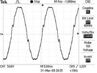
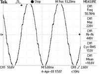
I was studying/working on inverter for the past few days. I though of taking an output wave form from the Pure Sine Wave Inverter 600VA. The sine wave amplitude was getting high and low gradually when ground probe wasn't connected, but with ground probe connected, it showed the correct waveform.

What is this, which is making this wave Go up and down? I'm curious about this.


rms of pwm triangle wave

This is the output waveform of load of a commerical SOHO Inverter 600VA, claiming it to be sine wave.
The waveform from 0W to 505W load changes it's shape. At even 60W load the waveform is changed a little bit from no load waveform shape. This inverter has feedback system, the feedback compensation doesn't look good to me.
Is THD a factor by which we can know the shape remains the same throughout the different load conditions?

Attach file is a series of JPG from my oscilloscope, i combine them into a GIF animated file.
 

animated ac signal

As a simple comment, you can't measure the inverters output voltage without a differential probe (or a single ended grounded output). The measurement shows an interference between inverter output and mains voltage and is effectively useless. At least a dual channel differential measurement should be tried.
 

    umery2k75

    Points: 2
    Helpful Answer Positive Rating
pwm for an ac signal

Hi FVM, does your comment applies to the GIF animation or to the video in which the wave grows and shrinks.

Added after 32 minutes:

Does differential voltage probe looks like these?

**broken link removed**
 

pwm to ac filter

My comment is primarly related to the video, where the floating probe operation is explicitely shown. It may be also a problem with the GIF animation, but I don't know about the conditions. I see, that there isn't a similar amplitude variation, but also some waveform details that rather suggest an artefact than a real measurement.

Yes, the Tektronix probe is a high end example of a differential probe. Third party products are available starting from about $500 I think. A small transformer would be a cheap replacement in this case, or as I suggested, a differential measurement with two standard probes.
 

    umery2k75

    Points: 2
    Helpful Answer Positive Rating
pwm signal for ac load

umery2k75 said:
In every article,I see regarding Sine wave Inverters, UPS.What they basically all do is to do variation of duty cycle in the PWM signal to provide a DC voltage across the load in a specific pattern, that appears to the load as an AC signal!
But why? Why it happens, how come the complex switching waveform appear as AC wave after passing through filter.


While you're past some of this already, there is a simple answer to this.

A sine wave is a sine wave. A sine wave around 5V has exactly the same AC component as a sine wave around 0V. Block the 5V DC part and you'll end up with essentially the same AC part, assuming the same amplitude and freq etc..

The reason to generate the sine above ground is simply for the ease of generation with standard 0-5V logic etc. Then filter and only couple the AC part and use it from there. It is a lot more complicated to make your normal logic parts generate a sine wave above and below ground, especially if you're wanting it microcontroller controlled..

Also look up 'magic sinewave'. A square wave has a lot of harmonics, the square edges can be thought of as a lot of sine waves overlapping. By using a higher frequency square wave with certain bit patterns, a lot of the harmonics can be cancelled out and you can get an output that is much closer to an actual sine wave. The remaining harmonics will be much higher order, and can be filtered out a lot easier..


Think about trying to get a sine wave out of a light bulb by flipping the switch. First you flip on and off, full on and full off. 50%, but not much of a smooth transition :) . So then you flip it fast, PWM, to make much smoother levels. Now the light gradually goes to full on, then to full off, etc.

But it's still not perfect! Even with PWM, when you first turn it on it will actually peak a little more than you wanted, and dark will go below where you wanted. Instead PWM even faster, and since ringing causes a higher initial peak than you want, turn it off a little early at first, then the ringing energy will take it to exactly where you want to be on the sine.

When you figure it all out, your 'turning on and off early' is compensating for harmonics. And the bit pattern to do it is the magic sine..

Instead of "1" for 50% then "0" for 50%, there is a 31 bit magic sine that was very good. Instead of just 1 and 0, you do it 31 times faster and do 31 bits, then the complementary 31 bits. The 1/0 could be filtered into nearly a sine, but it will take more and bigger components, with more wasted energy. The 31 bits magic sine takes faster processing and effort, but has much lower harmonics so is a lot easier to filter into a sine, with smaller components and less wasted energy.

Essentially the 1/0 has a lot of error in the signal vs a true sine, and by running faster and altering the pattern the 31 bit magic sine is precompensated to adjust most of the error out.

In some ways the discussion was past here, but this is the simple way to see it that is important to understand and carry forward.
 

changing an ac signal into a filtered dc signal

I would like to share, what new thing I learn't, especially if you don't have a good filter on your Inverter side.

This is the result of the symmetrical pulse train for 0-90 and 90-180 degrees.


It made me think twice,thrice....as what could be the reason? The pulses waveform were identical from 0-90 degrees to the set of waveform from 90-180 degrees, but still there was some peaks on the sides of the waveform?

Although one more intersting thing is that, the filter of inverter side only consist of a capacitor, which helped me realized an interesting fact, if I had a good filter made of inductor and capacitor. I wouldn't have realized this.I have seen few inverter which has good filter design and there pulses are symmetrical and their output are even pure sine wave.

I made a PWM pattern that wasn't symmetrical from 0-90 and from 90-180, that can produces the superb sine wave.In the picture below( I can even make it look more like sine wave and can smooth it's edges more),so I realized that you have to deal seperately when you're increasing power to the inverter and when decreasing the power, even at no load, you do this,when you don't have inductor on filter. These kinds of system helps decrease the cost of your filter even more, but increases more complexity for your waveform, that ain't symmetrical in any sense and that just can't be made with analog method, like in a standard manner, comparing the sine wave with triangular wave. The trade off lies in the filter, even Microchip UPS article used the symmetrical technique. I believe if more research is spent on PWM technique, filter size could be greatly reduce even more, by bringing the cutt off frequency even lower.As Microchip designers had put inductor on the inverter side, in this way they had get away with this effect, the wave got smoother due to inductor in place automatically, or they have to deal with rising and falling of wave seperately.

This is the result of unsymmetrical pulse train:


The pulses from 0-90 are entirely change from 90-180 degrees. I was thinking, this inverter is being design for resistive load for home,office. What if I was suppose to work with reactive load, the load would start giving energy back to the inverter, driving the waveform in an absurd wave and it's compensation factor would requires good time and skills for desiging.It's feedback system can drive a designer crazy!
 

duty cycle formula in pic16f73

umery2k75 said:
I made a PWM pattern that wasn't symmetrical from 0-90 and from 90-180, that can produces the superb sine wave.In the picture below( I can even make it look more like sine wave and can smooth it's edges more),so I realized that you have to deal seperately when you're increasing power to the inverter and when decreasing the power, even at no load, you do this,when you don't have inductor on filter. These kinds of system helps decrease the cost of your filter even more, but increases more complexity for your waveform, that ain't symmetrical in any sense and that just can't be made with analog method, like in a standard manner, comparing the sine wave with triangular wave. The trade off lies in the filter, even Microchip UPS article used the symmetrical technique. I believe if more research is spent on PWM technique, filter size could be greatly reduce even more, by bringing the cutt off frequency even lower.As Microchip designers had put inductor on the inverter side, in this way they had get away with this effect, the wave got smoother due to inductor in place automatically, or they have to deal with rising and falling of wave seperately.


You really need to read all of this, then go back and read my first post again..

They aren't getting away with anything, symmetrical is right. If you're outputting symmetrical and seeing different, then it's your code, other elements in your circuit, or the load causing it. Or your cap, loading AC with only a cap is wrong, caps and inductors cause lead/lag and this can lead to other effects. If you put a cap you will NEED an inductor to keep everything in phase.

You appear to be only looking at voltage.. You do realize that AC is generally looked at as voltage and current 90 degrees out of phase? While smoothing your voltage your fix is likely screwing your overall AC even more, you just aren't looking at it. Blind sine and proper filtering *IS* the best general answer in most cases. You're not even looking at the rest of what's going on to do something more complicated like active power factor correction.

There are things you aren't considering, and your experiments and thinking on it will just lead to incorrect ideas getting stuck in your head and being very hard to overcome later. Go find good sources and read everything on general AC you can find, and the magic sine stuff I was pointing you toward. Get right ideas and information in your head first before going down wrong roads.

Think of this, you know quite a bit on microcontrollers, in comparison to someone who's never heard of electricity and only knows about dirt they know nothing on microcontrollers. Well there are people who've spent their whole lives working with AC, in comparison you don't know dirt. You won't be coming up with anything actually new for 10 or 20 years at least, and doing anything other than availing yourself of all the good info that's already out there would be silly..

Even if you never heard of one and come up with a miracle idea for a flying machine, well it still isn't anything new, planes have been around for over 100 years, and people who've been designing planes starting from more current knowledge are 1000 times ahead of you. And silly to have been 'inventing' it instead of going out and seeing what was already there. You need to be reading the mountains and mountains of PWM/AC info, not trying to 'invent' it and giving yourself bad ideas..

General AC theory reactance etc.
PWM AC generation
Magic Sine
UPS
APC (Active Power factor correction, IE balancing the load)

You need to be reading all you can on these and how it all fits together. You don't understand what you're missing just looking at the voltage and trying to figure it all out from there, and again that partial understanding is only likely to lead to a whole lot of bad thinking. You will be 100 times better off to go read and get a lot of right ideas into your head first..


Just saying, I'm not holding a gun to your head, don't care that much. But if you get a bunch of bad ideas stuck in your head and takes you 5 or 10 years to get past them then you might end up wishing I had.

Done all I basically can, you've been pointed in the right direction, if you refuse to recognize it and check from there you'll only have your own refusal to be a proper man of science to blame.


That you said this like it was new and important should be a huge red flag to you..
" I believe if more research is spent on PWM technique, filter size could be greatly reduce even more, by bringing the cutt off frequency even lower."

You did see this in my post before?
" The 31 bits magic sine takes faster processing and effort, but has much lower harmonics so is a lot easier to filter into a sine, with smaller components and less wasted energy. "

It is not new, heck that is crap I know from the mid to late 80's and Don Lancaster's column in Radio Electronics, back when the Amiga was brand new and the C-64 was still quite current.

I'm a neophyte when it comes to AC, only knowing a bit here and there as needed from doing microcontrollers since the early 80's. If for even a second you didn't think you were the neophyte's neophyte when it comes to AC, you need to think again..

That isn't a put down, you are just a rank beginner on AC jumping ahead of their selves. You're thinking things like not having an inductor let you see something others haven't seen, and make it better. AC is extremely studied, literally millions of people have spent lifetimes working on it. You're not even considering more correct ideas, like the inductor is SUPPOSED to be there to balance the cap, and by not being there and only looking at voltage and making it 'smooth' without considering anything else you've probably broken the overall AC 10 times worse than it was with the glitch, you just don't see it because you're not even looking at it in an overall way correctly.

AC is a huge and complex subject on it's own, and essentially independent of any microcontroller knowledge you have. You need to go learn some on it as a separate subject before even beginning to think your uC knowledge carries over much at all. After a few months of reading you'll be amazed at just how little you knew..
 

    umery2k75

    Points: 2
    Helpful Answer Positive Rating
it* appears aktive power ac example

I am a complete newbie to these boards, so I apologize if my first post (this one) isn't very helpful, but your output frequency is appears to be around 40Hz, and it seems like your output wave form is oscillating slightly higher than that....is it possible you getting a phantom sin wave? Thats what we call it in the lab when the oscilloscope overlays the 60Hz signal used to power it over the output due to bad grounding within the scope when your testing frequencies close to 60
 

ac sine wave animation

No, in one wave I set frequency around 50.76 and in other 49.
 

Status
Not open for further replies.

Similar threads

Part and Inventory Search

Welcome to EDABoard.com

Sponsor

Back
Top