Continue to Site

Welcome to EDAboard.com

Welcome to our site! EDAboard.com is an international Electronics Discussion Forum focused on EDA software, circuits, schematics, books, theory, papers, asic, pld, 8051, DSP, Network, RF, Analog Design, PCB, Service Manuals... and a whole lot more! To participate you need to register. Registration is free. Click here to register now.

Why should a Schottky diode be connected in parallel to the resistor?

Status
Not open for further replies.

hannover90

Member level 4
Joined
Dec 8, 2009
Messages
70
Helped
0
Reputation
0
Reaction score
0
Trophy points
1,286
Location
Germany
Activity points
1,784
Why schould a Schottky diode be connected in parallel to resistor?

In some over voltage (or spikes) protections, a Schottky diode is used, which is connected in parallel to a resistor.
I can not understand the role of the resistor.

Could someone explain to me, please? Thanks
 

Re: Why schould a Schottky diode be connected in parallel to resistor?

That's not a typical connection.
Show an example circuit doing that.
 

Re: Why schould a Schottky diode be connected in parallel to resistor?

In some over voltage (or spikes) protections, a Schottky diode is used, which is connected in parallel to a resistor.
I can not understand the role of the resistor.

Could someone explain to me, please? Thanks

Without seeing your schematic it's impossible to answer. Maybe you've got a diode placed across a resistor, rather than the other way around.
 

Re: Why schould a Schottky diode be connected in parallel to resistor?

Without seeing your schematic it's impossible to answer. Maybe you've got a diode placed across a resistor, rather than the other way around.

Thanks for your reply.
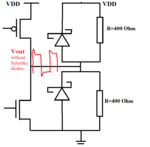
In the attachment is an example of a driver with two schottky diodes for an over voltage protection.
I understand, how the schottky diodes work but I can not understand, why should resistors be connected to these diodes.


Schottkydiode.png
 
Last edited:

Re: Why schould a Schottky diode be connected in parallel to resistor?

The resistors may serve a purpose if the driver is tri-stated.
 

Re: Why schould a Schottky diode be connected in parallel to resistor?

Thanks for your answer.
Because of parasitic effects, the spikes appear on Vout.
The Schottky diodes prevents the negative [spikes < (0 V-VD of Schottky] and positive spikes [spikes > (VDD+ VD of Schottky].
But which role has resistors??
 

Re: Why schould a Schottky diode be connected in parallel to resistor?

At best they might be a shunt termination meant to
match a transmission line characteristic impedance.

At worst they are just a stupid illustration that only
burns static power.
 

Re: Why schould a Schottky diode be connected in parallel to resistor?

I like FvM's answer. The resistors will hold the output voltage at half the rail if both FETs are off.
 

Re: Why schould a Schottky diode be connected in parallel to resistor?

......... Maybe you've got a diode placed across a resistor, rather than the other way around.
How are those two different other than semantically? :???:
 

Re: Why schould a Schottky diode be connected in parallel to resistor?

Given that the resistors are the same value, a practical use would be for trying to match a characteristic impedance. If they were different values, I'd suggest it would be for the output
to be at a specific DC bias when the driver is not being driven (tri-stated). The diodes could in most cases accomplish the midpoint-level bias point by themselves, depending on current requirements.
 

Re: Why schould a Schottky diode be connected in parallel to resistor?

How are those two different other than semantically? :???:
It's also functionality. If you're trying to limit a voltage across a resistor, you'd put a diode across it. The op asked 'why put a resistor across a diode'. It's the same difference as putting a house under a roof.
 

Status
Not open for further replies.

Similar threads

Part and Inventory Search

Welcome to EDABoard.com

Sponsor

Back
Top