Continue to Site

Welcome to EDAboard.com

Welcome to our site! EDAboard.com is an international Electronics Discussion Forum focused on EDA software, circuits, schematics, books, theory, papers, asic, pld, 8051, DSP, Network, RF, Analog Design, PCB, Service Manuals... and a whole lot more! To participate you need to register. Registration is free. Click here to register now.

why quarter wavelength for directional coupler?

Status
Not open for further replies.

kwagjj

Member level 1
Member level 1
Joined
Apr 13, 2009
Messages
32
Helped
0
Reputation
0
Reaction score
0
Trophy points
1,286
Activity points
1,539
for directional couplers which is nothing but two parallel microstrips adjacent to each other, I can't understand why it has to be quarter wavelength.

My guess is that since coupling is merely interacting with the other microstrip through E, H fields, there isn't any need to be quarter wavelength. The longer, then more coupling will occur and more power will be transferred.

But every google search that I look up, it says that directional couplers use quarter wavelength but it doesn't say why. What is wrong with my guess?
 

Your understand of theory is right: it does not have to be 1/4 wavelength for a directional coupler.

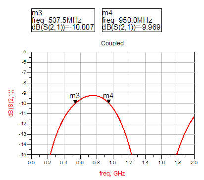
In general, coupling will change with frequency. If you make the coupler 1/4 wavelength, you can reach a nice bandwidth where coupling does not change too much.

7004336900_1414586685.png
 
hmm.. your answer kind of answers some part of my question but it also confuses me again on the other.

okay you said the length doesn't necessary have to be quarter wavelength to provide good coupling.
despite this, you still mention that the coupler is 'good' to have a length equal to quarter wavelength. Even though the purpose of configuring the length is to get a nice BW of relatively high coupling for a frequency range of interest,

still, even in the graph that you've shown, the 'nice BW' range seems to repeat along frequency.

I wanted to know if why coupling repeats by frequency and I assume that this has to do something with the length of the TL.
for example, when the frequency is a multiple of the fundamental frequency that has a quarter wavelength equal to the given TL length, then the coupling is increased.
how can I explain this repeating tendency?
why is coupling enhanced when the current frequency's quarter wavelength is a 1/N (N=integer) of the TL length?
 

Next to the coupling, you should also consider the matching

True, but that's independent of the coupler length, as explained in the document that you linked:

from the link said:
To summarize, with the mentioned assumptions:

i) Port 4 which is named also as Isolated port, always has a zero output, without being dependent of the electrical length of the coupling region. Major cause of poor isolation in practical circuits are unequal phase velocities of even and odd mode.

ii) The input at each port is matched to the feed line characteristic impedance, Z0, irrespective of the electrical length.

iii) The total output power equals the input power.

iv) The maximum coupling to port 2 occurs at the frequency that gives a quarter wave coupling length which is l/4. This is the mid-band frequency and due to this property, this couplers are also known as quarter-wave couplers.

v) At the maximum coupling frequency, there is a 90° phase difference between the voltages at port 2 and port 3. Such a coupler can also be described as quadrature coupler.

vi)At the frequencies other than maximum coupling frequency (design frequency)

the coupling of the coupler can be found from |V3(q)|.
 

Status
Not open for further replies.

Part and Inventory Search

Welcome to EDABoard.com

Sponsor

Back
Top