poorren
Junior Member level 3
Hi guys,
The question comes from installing a rod antenna to homebrew wideband receiver(20Mhz-1Ghz).
I built this receiver with spectrum analysis ability. so, I could see anything in the band.
In initial phase of work, I use an used signal source from R&S to test the receiver. The spectrum seems to be clear and noise plateau is relatively flat. Today, I install a rod antenna, see pic1,

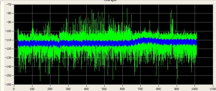
when i try to look the real world. The real world sounds to too roaring in VHF band. see pic2.

(line in blue is unload antenna's spectrum, green line is spectrum after antenna installation.)
It's obvious that the antenna pick up an noise hump in vhf band. I was very curious why there are so much noise or spectrum product in vhf. I install the same antenna to a HP's spectrum analyzer. To compare that, the HP's result seems to be good, and the noise looks much better in vhf band.
I made some experiment on this antenna and found that the antenna's ground play a key role in this vhf noise hump. The result is that if I directly contact the rod antenna's ground to HP analyzer's ground (RF input connector), the hump will disappear without doubt.
see below pic.

However, if I directly contact my receiver's shield box (ie., power ground) to HP analyzer's ground. The hump would reduce, but won't as effective as directly contact antenna's ground to spectrum analyzer. Humm... I must say, I don't know why, and I want to consult.
Tow things I must to mention are
1. rod antenna is connected to my receiver with SMA terminated cable, the cable seems good. I once directly plug antenna to receiver's antenna port. The hump persists there.
2. my receiver is powered by 18V+ AC/DC converter, the DC's negative seems to internally short to 220V AC's GND in converter itself. And my receiver shared the same AC power supply board with spectrum analyzer. So, I guess they shares the same ground.
I'm not sure why this happens, but my receiver seems to be noisy in face of rod antenna.
Any idea or any answer would be welcome. Thanks advance!
And I would continue to try after my dinner. And hope to know why.
Jeff
The question comes from installing a rod antenna to homebrew wideband receiver(20Mhz-1Ghz).
I built this receiver with spectrum analysis ability. so, I could see anything in the band.
In initial phase of work, I use an used signal source from R&S to test the receiver. The spectrum seems to be clear and noise plateau is relatively flat. Today, I install a rod antenna, see pic1,

when i try to look the real world. The real world sounds to too roaring in VHF band. see pic2.

(line in blue is unload antenna's spectrum, green line is spectrum after antenna installation.)
It's obvious that the antenna pick up an noise hump in vhf band. I was very curious why there are so much noise or spectrum product in vhf. I install the same antenna to a HP's spectrum analyzer. To compare that, the HP's result seems to be good, and the noise looks much better in vhf band.
I made some experiment on this antenna and found that the antenna's ground play a key role in this vhf noise hump. The result is that if I directly contact the rod antenna's ground to HP analyzer's ground (RF input connector), the hump will disappear without doubt.
see below pic.
However, if I directly contact my receiver's shield box (ie., power ground) to HP analyzer's ground. The hump would reduce, but won't as effective as directly contact antenna's ground to spectrum analyzer. Humm... I must say, I don't know why, and I want to consult.
Tow things I must to mention are
1. rod antenna is connected to my receiver with SMA terminated cable, the cable seems good. I once directly plug antenna to receiver's antenna port. The hump persists there.
2. my receiver is powered by 18V+ AC/DC converter, the DC's negative seems to internally short to 220V AC's GND in converter itself. And my receiver shared the same AC power supply board with spectrum analyzer. So, I guess they shares the same ground.
I'm not sure why this happens, but my receiver seems to be noisy in face of rod antenna.
Any idea or any answer would be welcome. Thanks advance!
And I would continue to try after my dinner. And hope to know why.
Jeff