Continue to Site

Welcome to EDAboard.com

Welcome to our site! EDAboard.com is an international Electronics Discussion Forum focused on EDA software, circuits, schematics, books, theory, papers, asic, pld, 8051, DSP, Network, RF, Analog Design, PCB, Service Manuals... and a whole lot more! To participate you need to register. Registration is free. Click here to register now.

which of the antennas has the better radiation characteristic?

Status
Not open for further replies.

project.email

Member level 4
Joined
May 25, 2007
Messages
77
Helped
8
Reputation
16
Reaction score
8
Trophy points
1,288
Activity points
1,845
Dear friends, Hi
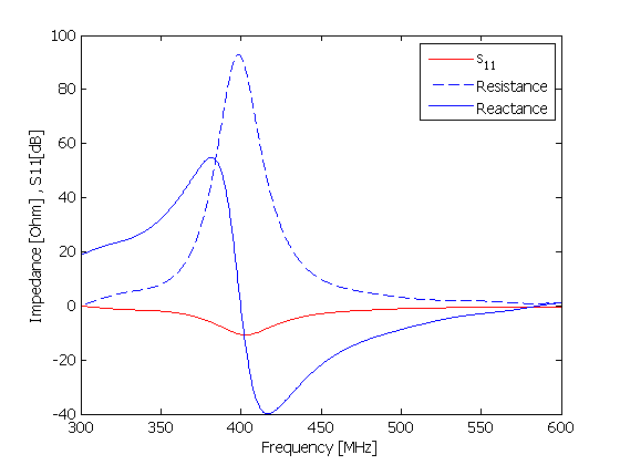
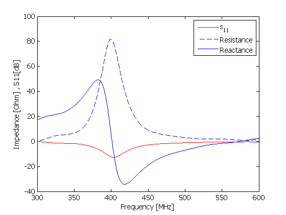
I have two different antennas with the following Z ans S11.
I know that an antenna radiates when the image component of the input impedance be equal zero.
I want to know in theses figures which antenna has the better radiation properties?
and why?dose it possible just by looking to the impedance characteristic understand the radiation characteristic,or not?


Hello Project

From the looks of what you have uploaded here.it's the impedance of the antenna,both seem to resonate, at resonance the resistance of the first antenna is above 90 Ohms and the second is close to 80 Ohm's from these figures we can figure out how better your power will be transmitted and not the actual radiation characteristics.

from the s11 parameters.it is obvious that second antenna has a better reflection coefficient. so less power will be reflected back to source.

so obviously antenna two will have a edge over the first antenna in terms of radiation at resonant frequency, but to say what exactly will be radiation characteristics it will be definitely difficult to answer.

Regards
Chachito
 
"which of the antennas has the better radiation characteristic?" It depends on what you require, could be point to point, i.e. narrow power beam or broadcasting where you want omni directional with no power going vertically. Unfortunately, the match of the aerial tells us nothing about its radiation characteristic, just how easy it is to match to. Its worth while throwing away a lot of power in the match if all the remaining power is being useful.
Frank
 
In addition to the points altready mentioned. Assuming the intended operation frequency is 433 MHz, non of the antennas is tuned correctly. They s11 characteristic of both doesn't look much different anyway, but you would preferably use a matching network to connect it to a 50 ohm transmitter. For 433 MHz, both should be shortened.
 
"which of the antennas has the better radiation characteristic?" It depends on what you require, could be point to point, i.e. narrow power beam or broadcasting where you want omni directional with no power going vertically. Unfortunately, the match of the aerial tells us nothing about its radiation characteristic, just how easy it is to match to. Its worth while throwing away a lot of power in the match if all the remaining power is being useful.
Frank
Dear Frank thanks for your reply.these antenna are embedded in a lossy medium and what's important to me is the SAR(specific absorption rate) of these antennas
but it's also important to know which of them has better radiation characteristic.I konw the radiation characteristic is determined in terms of radiation efficiency,Gain and directivity correct?but what are the whole things that these plots tell us? These are only the Return loss and the impedance chracteristic.
As dear Chachito has mentioned I'm agree that, they tell us about the reflected power and the good matching at the operating frquency which is 402-405MHz.If the Return Loss be more minus in the magnitude the reflected power will be more little(i.e -10dB cause to P_reflected=0.1 and -20dB cause to P_reflected=0.01,suppose the delivered power be 1W ).but what about the Impedance value?I think if we look to the antenna in term of it's Transmission line model,when we feed the antenna with a 50 ohm feeding it's better to have a good matching that the Impedance value be about 50 ohm too.no more no less.correct?
If the impedance being different with 50 ohm , we will have mismatch in this case.
so I conclude that if the feeding is 50 ohm the better Impedance value should be about 50 ohm to the more better matching,correct?

In addition to the points altready mentioned. Assuming the intended operation frequency is 433 MHz, non of the antennas is tuned correctly. They s11 characteristic of both doesn't look much different anyway, but you would preferably use a matching network to connect it to a 50 ohm transmitter. For 433 MHz, both should be shortened.

Dear FvM ,your replies are always leading for me.
The desire frequency is about 402-405MHz so both of these plots with the mentioned Return loss have good matching for this frequency band.correct?
I wanted to know what exactly the Impedance plot exactly tell us?Dose it tell any thing about the radiation pattern properties?I think it only tell us about the quality of feeding .
Are you agree with my above reply?
Regards.
 

Parameters revealed by the plots are actual antenna impedance (80 respectively 90 ohm), center frequency and bandwidth. In case of electrically small antennas of known geometry, bandwidth may allow additional conclusions about losses. Wider bandwith raises a suspect of higher losses in this case.

But strictly spoken, the diagrams don't tell, which part of the input power is radiated and which ist turned into losses.
 
Status
Not open for further replies.

Part and Inventory Search

Welcome to EDABoard.com

Sponsor

Back
Top