Continue to Site
Follow along with the video below to see how to install our site as a web app on your home screen.
Note: This feature may not be available in some browsers.
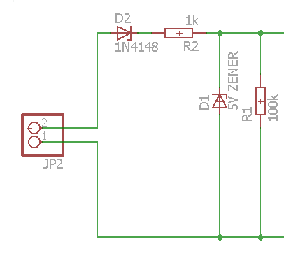
But waaaaaaait.... I was going to use ADC to detect the sine rise...
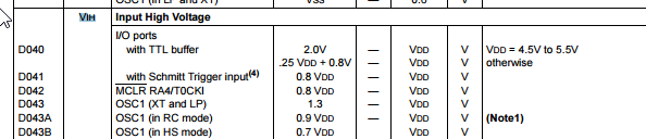
Does it makes sense to check TTL voltage levels while I want to use ADC?
Yes. Every input signal >2.0V means HIGH.My VDD is 5V so it's simply 2V?
No! You have to look for V_IL to know what the valid levels for LOW are.and 1.9V at pin means LOW?
If I dont have 4.7V Zener diode, can I use 3.3V one?
ADDED:
BTW. I don´t recommend using ADC. It is slow compared to logic levels or comparator input. But if this is no problem for your application then for sure you may use it.
Klaus
Precision...I need to detect the sine rise precisely
Code C - [expand]
Hi,
it seems you control the ADC just in the main loop without known/fixed timing.
I strongly recommend to use a fixed ADC sampling rate and an interrupt driven processing of the ADC values.
Klaus
Code C - [expand]
Code C - [expand]
Code C - [expand]
Code C - [expand]