umery2k75
Advanced Member level 1
multisim giving me wrong results
I was just playing with the multisim and I thought of making a series circuit consisting of two capacitors just for nothing.
C1=0.1uF
C2=0.2uF
Vcc=12V
so Vc1=C2/(C1+C2)*Vcc=8V
Vc2=C1/(C1+C2)*Vcc=4V
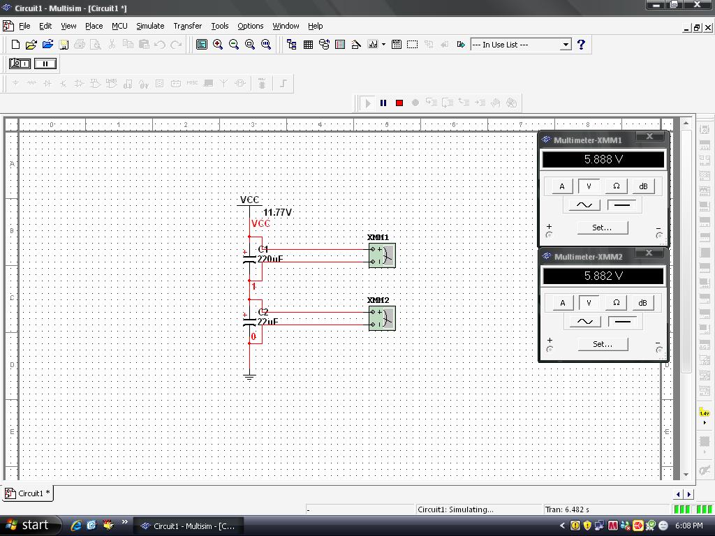
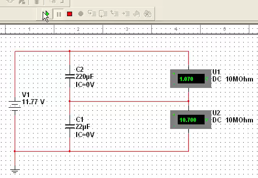
I must have 8V and 4V across capacitors, but MultiSim was showing 6.003V and 5.997V.
What could be wrong? I have tried both the polar and the non-polar capacitors.
I was just playing with the multisim and I thought of making a series circuit consisting of two capacitors just for nothing.
C1=0.1uF
C2=0.2uF
Vcc=12V
so Vc1=C2/(C1+C2)*Vcc=8V
Vc2=C1/(C1+C2)*Vcc=4V
I must have 8V and 4V across capacitors, but MultiSim was showing 6.003V and 5.997V.
What could be wrong? I have tried both the polar and the non-polar capacitors.