daraemon_liu
Junior Member level 1

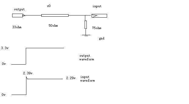
The circuit is shown in the attachment,and the signal transformed is high speed signal,which means the TL impedance is 50 ohm for the switch edge of the signal,however it is 0 ohm for the high level of the signal. The output resistance is about 33 ohm,there is also a 75 ohm parallel terminated resistor at the end of the TL for absorbing the reflection.
So I was wondering what is the waveform will be at the load?
I do a calculation as below:
(1) for the rising edge:
reflection ratio=(75-50)/(75+50)=0.2
amplitude at the end =3.3*50*(1+0.2)/(33+50)=2.39v
(2) for the high level:
amplitude at the end =3.3*75/(33+75)=2.29v
So I think the waveform is described as the attachment ,which has a overshot of the rising edge about 0.1V.
Can anyone tell me whether I was right or not? TKS!
---------- Post added at 11:24 ---------- Previous post was at 11:21 ----------

