Continue to Site

Welcome to EDAboard.com

Welcome to our site! EDAboard.com is an international Electronics Discussion Forum focused on EDA software, circuits, schematics, books, theory, papers, asic, pld, 8051, DSP, Network, RF, Analog Design, PCB, Service Manuals... and a whole lot more! To participate you need to register. Registration is free. Click here to register now.

[SOLVED] what kind of problems can making neutral your ground cause

Status
Not open for further replies.

jishnuprakash

Junior Member level 2
Joined
Feb 21, 2022
Messages
22
Helped
0
Reputation
0
Reaction score
0
Trophy points
1
Activity points
144
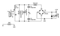
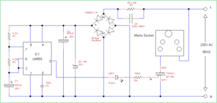
while going through the circuit i saw that in this circuit neutral is connected to ground,
what kind of problem can this cause?, is this a normal procedure?, should i be using Bridge rectifier for better reliability

AD1421, AD1421E, CE615, CE617 ctd-a-schematic Model (1).jpg
 

hopefully this is just a drawing artifact / error and neutral is not really connected to earth somewhere inside the equipment ....
 

hopefully this is just a drawing artifact / error and neutral is not really connected to earth somewhere inside the equipment ....
no earth for this circuit
--- Updated ---

hopefully this is just a drawing artifact / error and neutral is not really connected to earth somewhere inside the equipment ....
neutral is connected to ground, I checked it in PCB
 

this is on timer device which is enclosed in plastic shell so no shocking, my question is does this going to affect reliability anyway, is it better to go with bridge rectifier in reliability standpoint,
 

You should clarify that "ground" means common ground of the logic circuit. Connecting it to neutral is required if you want to drive triacs without isolation (gate transformer, opto couplers).
 

Hi,

Genearlly a connection of a PCB_GND to a high voltage wire is no problem.
You could connect your cellular phone's GND to a live high voltage transmission line, while the cellular phone still will work.
You could also sit on the same wire (like a bird) while operating the phone ..... whitout danger .... as long as you don't touch any signal with different voltage.

Klaus
 

Thank you all for clearing my doubt, can you suggest any modification / improvement to increase reliability
is it better to go with isolation and why?
 

Hi,

I don´t know how you want to use a bridge rectifier in this circuit...
.. and how you think it should improve "reliability".

Please explain. Draw a sketch..

Klaus
 

Hi,
I was asking whether using isolation between triac and driving circuit is better than current method,
would it improve switching and life, in case of bridge rectifier i was suggesting to used that to convert AC into DC instead of existing two transistors
 

Attachments

  • CTD_V2 (1).jpg
    CTD_V2 (1).jpg
    19 KB · Views: 110

Hi,

firstly: a triac is an AC switch ... using a bridge rectifier "may" make the triac to never switch OFF.
And I don´t get your idea about the meaning of "better". Better reliability? Generally ... adding parts rather increase the chance for error than decrease.
And a rectifer causes additional power to be dissipated = heat. More heat usually is the opposite of "more reliable". And controlling a triac "after" (guessing) a bridge rectifier causes a lot of additional hardware effort.

Sadly I can´t see how the bridge rectifier circuit relates to the circuit of post#1 at all.
It´s not clear how you want to join both schematics.

So all the above is guessing.
Maybe give more elaborated informations and ask a more detailed question.

Klaus
 

Hi,
I am controlling Triac using a Timer circuit, which is powerd by DC, so what i was suggesting is to switch Triac using AN MOC, i was wondering which could reduce problems and give better control , since you have suggested more components only going to increase the chance of failure i guess better stick with current design,
 

Attachments

  • AC-outlet-with-Timer (1).png
    AC-outlet-with-Timer (1).png
    11.6 KB · Views: 112

Hi,

referring to the schematic of post#12:

This is a simple, cheap but good solution. If you don´t need isolation ... I don´t recomend to add isolation,
Functionally the gate of the triac is getting controlled in a rather clean way .. and that´s a good thing.

Here the rectifier has nothing to do with triac or triac control. It´s just used as power supply for the NE555.

Now you ask about MOC. (Isolation is one benefit .. but not needed here)
But you also talk about "reduce problems".
Here I see one feature of some MOC devices: The zero cross switching feature. Zero cross switching reduces EMI problems but on the other hand it may cause high inrush current when the load is a transformer or a motor.
Using this circuit with the shown "mains socket" ... is rather critical, because the user may connect any load. From high capacitive SMPS to high inductive transformers.

In this case it has to be decidedd if one can stand the eventually high inrush current or the higher EMI noise.
In either case consider to add an EMI filter and a snubber.

Isolation gives safety. But in your case just in the laboratory during development. As soon as the circuit is covered in a plasitic case the improvement in safety is meaningless.

Klaus
 
Status
Not open for further replies.

Part and Inventory Search

Welcome to EDABoard.com

Sponsor

Back
Top