Continue to Site

Welcome to EDAboard.com

Welcome to our site! EDAboard.com is an international Electronics Discussion Forum focused on EDA software, circuits, schematics, books, theory, papers, asic, pld, 8051, DSP, Network, RF, Analog Design, PCB, Service Manuals... and a whole lot more! To participate you need to register. Registration is free. Click here to register now.

What is this board for?

Status
Not open for further replies.

VTI_16V

Member level 1
Joined
Nov 25, 2019
Messages
38
Helped
0
Reputation
0
Reaction score
0
Trophy points
6
Activity points
386
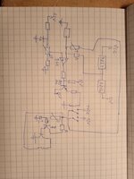
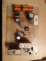
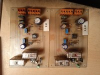
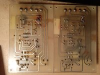
Hello. I received some 2 boards from some kind of old battery charger. I don't know are there any other boards that should be related to it. I drawed some kind of schematics, maybe i made some minor mistakes :(... Should this be some kind of comparator when switcher the charging on and off? When i measure voltage on 741 on pin 3 is always ground, and pin 2 varies with input voltage. The same thing on both boards. When I connect it to supply, whatever voltage I give from 20-35V it is always the same result. First relay closes immediately, and second after few seconds. Can anybody figure out what this actually does and how is related to some kind of 24V charging system? And explain maybe?
 

Attachments

  • IMG_20220216_190318.jpg
    IMG_20220216_190318.jpg
    2.3 MB · Views: 170
  • IMG_20220216_190328_1.jpg
    IMG_20220216_190328_1.jpg
    3.5 MB · Views: 167
  • IMG_20220216_190339_1.jpg
    IMG_20220216_190339_1.jpg
    2.2 MB · Views: 157
  • IMG_20220216_190350_1.jpg
    IMG_20220216_190350_1.jpg
    3.3 MB · Views: 162
  • IMG_20220216_190419_1.jpg
    IMG_20220216_190419_1.jpg
    3.3 MB · Views: 164
  • IMG_20220216_190429_1.jpg
    IMG_20220216_190429_1.jpg
    3.1 MB · Views: 161
Last edited:

Merely speculation...
Some chargers let you choose options.
Example, battery voltage 6 or 12 (or 24).
Example, charge rate maximum or regulated.

I have a car battery charger rated 10 Amps. On the front is a switch choosing between two modes, automatic or manual.
Manual delivers maximum current indefinitely. The Ampere gauge goes to 10A and stays there. It's a fast rate capable of overcharging a battery.

Automatic mode reduces charge rate gradually as battery voltage rises.
The Ampere needle starts at a high value, jittering continually as charging drops to a trickle.

Perhaps your system also has options?
 

Hi,

Basically it's a threshold level detector with hystesis.
One pot is for level, the other for hysteresis.

Maybe like Brad wrote a 12V/24V switch
Maybe a CC/CV switch.

****

Wow, over 17MBytes ... I can't remember a post with higher file size. 0.5MBytes in total surely could be sufficient.
Even with rather good internet rate it takes several seconds to load one picture, I wonder how long it takes in areas with low internet bandwidth.

Klaus
 

Unfortunately I didn't saw the whole system, but as I was told it is from old charger which can charge with 40 Amps or nothing (charging goes over contactor), it doesn't have regulation... Well I didn't write down the resistance values, I could do it. The thing that confuses me is that pin 3 of comparator is always at ground level on both of them. And I know for sure that one board is working fine as guy told me... So if pin 3 is always ground no matter what voltage I apply (I went beyond 30V and nothing changed) that would mean that this device will close relay every time when voltage is applied? Than I can't understand its purpose. But for sure nobody didn't messed with potentiometers...
 

Status
Not open for further replies.

Part and Inventory Search

Welcome to EDABoard.com

Sponsor

Back
Top