Continue to Site

Welcome to EDAboard.com

Welcome to our site! EDAboard.com is an international Electronics Discussion Forum focused on EDA software, circuits, schematics, books, theory, papers, asic, pld, 8051, DSP, Network, RF, Analog Design, PCB, Service Manuals... and a whole lot more! To participate you need to register. Registration is free. Click here to register now.

What cause a crystal paused?

Status
Not open for further replies.
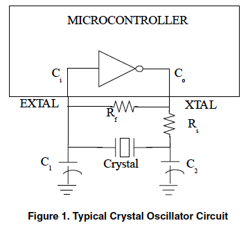
I have contacted the support engineer of the MCU, he confirmed the load capacitor value I used is correct (I use 18pF). And it is a mistake on their datasheet saying that no load capacitor is needed.

However, when I tried to decrease the load capacitor value to 12pF, I found the problem gone.

Another observation is that the board has a LCD, when I remove the LCD on few of the boards, the problem also gone. But this does not work on all of my boards.

In fact we have made over 200pcs of this board before and I did not see this problem. This problem occurs only recently.

Therefore I suspect that something is not compliant to the datasheet, the MCU or the crystal. Or my PCBA has a relatively large stray capacitance (so I need to use a lower value load capacitor and removing the LCD will decrease the stray capacitance a bit)? I do not know how to measure the stray capcitance on my PCB...
 

However, when I tried to decrease the load capacitor value to 12pF, I found the problem gone.

I guess this is normal batch to batch variation in the manufacturing process. Are you using the crystal in the fundamental or overtone mode? How the PCB stray capacitance will couple with the crystal? I shall tend to agree with your observation that something is not compliant to the datasheet.
 

How can I check if it is the crystal problem?

I set my scope for X/Y display. I applied square waves to one lead of the crystal. I fed this to one scope lead (one axis). The other scope lead (other axis) sensed output at the crystal's other lead. As I recall this was delayed by either 1/32000 or 1/64000 of a second. (I'm not sure the timescale can be read in X/Y mode.)

A good crystal can be expected to send strong delayed output, or else a well-defined waveform.
A bad crystal can be expected to send weak delayed output, or else a less distinct waveform.

I only did brief tests on crystals, so I'm no expert. This test should be done with very low volt/current levels, to avoid altering the crystal's characteristics.
 

Hi,

Your description with the LCD makes me think there is a serious PCB layout problem.

Could you post it, so we can check it.

Ground plane is solid? All IC VCC pins have fast ceramics capacitors?
What kind of LCD is it? Simple glass, small alphanumeric, large graphic?

Klaus
 

The pdf from post #15 has this typical schematic for an MCU. It resembles the circuit I tried (although I used a plain inverter gate, not an MCU).

2695249800_1459364657.png


Normally I see MCU schematics without the resistors near the crystal. Therefore I suppose an MCU contains them internally. Their values may have a lot to do with success of the crystal oscillating. Maybe they are easy to alter through accidental exposure to excess voltage or current?

- - - Updated - - -

Therefore once the crystal, or the MCU, becomes suspect, it could be worth trying to add various resistors at different points, in hopes of making oscillations more stable, and easier to start up?

I lowered the load capacitor value on some boards, some works (aka A) and some does not work (aka B). And then I added a 1M resistor accross the crystal pins on the (B) boards, they works! Why the resistor can help?
 

Hi,

Why the resistor can help?
it seems you did not read our posts.

In Post#15 there is a document discussing your problem and how to solve it.
On page3 there is the description about Rf.

Klaus
 

Hi,


it seems you did not read our posts.

In Post#15 there is a document discussing your problem and how to solve it.
On page3 there is the description about Rf.

Klaus

It says if the microcontroller has an internal Rf, we do not need an external one. The engineer from the microcontroller has reviewed the circuit with the datasheet, they did not mention that we need an external Rf, so I think they have an internal resistor already.
 

It says if the microcontroller has an internal Rf, we do not need an external one. The engineer from the microcontroller has reviewed the circuit with the datasheet, they did not mention that we need an external Rf, so I think they have an internal resistor already.

It is good that I learn from this document that it says the characteristic of each crystal can be very different. I just got another crystal, it is the can type through hole crystal with max. ESR 30K ohm. My original one is SMD type and has max. 50K ohm ESR, same load capacitance stated. I tested this new crystal on some of my board and it works!

But now I have another problem. The original SMD type crystal have been used in over 200pcs boards and I could not see the problem, Every things seem were designed according to the datasheet, and confirmed by the application engineer. In pratical, how can I tell this can type crystal is also good?
 

Hi,

what controller is it exactely?
Manufacturer and complete ordering code?

**
I just came across a Feescale KINETIS ARM M0 datasheet and I fond this:
M0_osc.png
So if this is the same with your microcontroller, then - as long as you don´t need that very low power mode - I recommend to use HGO mode.

It is way more stable as the low power mode. (BTW: in low power mode Rf is not used.)

Klaus
 

Hi,

what controller is it exactely?
Manufacturer and complete ordering code?

**
I just came across a Feescale KINETIS ARM M0 datasheet and I fond this:
View attachment 127826
So if this is the same with your microcontroller, then - as long as you don´t need that very low power mode - I recommend to use HGO mode.

It is way more stable as the low power mode. (BTW: in low power mode Rf is not used.)

Klaus

The microcontroller is Atmel SAMD20J18.

The application engineer from Atmel admit that there is a bug on the microcontroller's drive level configuration. It is fixed at 3uW. The crstal rated at 1uW.

If it is the root cause, I would like to ask if the Rf resistor can solve the problem reliably?

Thanks
 

It is fixed at 3uW. The crstal rated at 1uW....

As long as the available drive level is higher than the required drive level, it is easy to fix with a series resistor. The other way will be tricky, if not impossible.
 

I would like to check the driving level on a real microcontroller, so I try to check the microcontroller oscillator output pin by an oscilloscope. However I can only see a relatively constant voltage at about 0.3V, rather than a distorted sine wave that I expected. I have used a 100X probe and a ground spring. And I have tested on several PCBs. Why I cannot see the oscillation? Also why the voltage is so low?
 

Hi,

did you ever say at what pins you connect the xtal and what your xtal oscillator setting is?

Do you use the automatic amplitude control feature? (errata).

Klaus
 

Status
Not open for further replies.

Similar threads

Part and Inventory Search

Welcome to EDABoard.com

Sponsor

Back
Top