Continue to Site

Welcome to EDAboard.com

Welcome to our site! EDAboard.com is an international Electronics Discussion Forum focused on EDA software, circuits, schematics, books, theory, papers, asic, pld, 8051, DSP, Network, RF, Analog Design, PCB, Service Manuals... and a whole lot more! To participate you need to register. Registration is free. Click here to register now.

What are tubes ? capacitors or resistors ?

Status
Not open for further replies.

NSunJ

Junior Member level 1
Joined
Feb 2, 2015
Messages
16
Helped
0
Reputation
0
Reaction score
0
Trophy points
1
Activity points
107
What are tubes ? are they capacitors or resistors ? or both ?

What are tubes ? are they capacitors or resistors ? or both ?

How can I create saturation without using tubes ?
 
Last edited:
That's a strange question. Most of the time we talk about 'tubes' we refer to vacuum tubes which are thermionic devices. Capacitors and resistors are not related to 'tubes' in any way. Saturation in electronic terms means "at the maximum limit of conduction" so again it is unconnected with 'tubes'.

Where did you see these references?

Brian.

I was wandering about this since I could not find such reference, thanks. What is the function of vacuum tubes in circuit design to amplify audio ?
 
Last edited:

I was wandering about this since I could not find such reference, thanks. What is the function of vacuum tubes in circuit design to amplify audio ?

Oh, boy! You made me back almost a century!
Before semiconductor devices we had vacuum tubes. Some still survive in audio amplifiers as some people believe such amplifiers generate a better sound.
Please go to a library and find electronic or radio textbooks and magazines date before ~1960.
I think I could not give you a reasonable information on vacuum tubes here in short.
Try the Edaboard thread Vacuum Tubes, History
 

Vacuum tubes or 'thermionic valves' are the predescessors of transistors, in most applications they were phased out about 40 years ago because of their relative inefficiency and need for high voltages. Some people argue that they sound better than transistors in audio amplifiers although there is little technical proof that is true. A few enthusiasts still use them and they are still manufactured in small quantities but they are many times more expensive than their modern semiconductor replacements.

I don't know of any new designs that have used them in maybe the past 30 years.

Brian.
 

Vacuum tubes burn out or quickly wear out, solid state devices do not.
Some rock bands replace the vacuum tubes in their amplifiers before every show.

I built a vacuum tube amplifier in 1962 from a kit. It sounded good when new but after 3 months it sounded bad. An expensive amplifier manufacturer set up a clinic at the audio store to test your amplifier to show that their amplifier is much better. My 3 months old amplifier tested with terrible distortion so I replaced its vacuum tubes and its distortion almost vanished. The distortion returned a few months later when I bought the solid state FM stereo receiver that I still play and still sounds good today.
 

"tubes" AKA valves were used up to recently for high power transmission. I believe that the highest powered TV transmitters in the UK still use thermionic devices (Klystrodes). Also I wonder if stations like voice of America (are they still about?) would be using hundreds of kilowatts of power and the complexity and cost of adding hundreds of kilowatt solid state modules would not make it a worth while exercise.
Traveling wave tubes are used for SHF uplinks to satellites and were used in satellites.
Frank
 

TWTs still are the technology of choice for space based microwave apps, LDMOS might take over in the next generation of birds, but space qualifying the things has been problematic.

While you would think that a 100KW class solid state amplifier would be a pain (And it is), it turns out that the enery savings from going solid state can be sufficient to make the pain entirely worth it in very short order.

As far as valves (Tubes) of the conventional sort go, think junction fet operating at an order of magnitude or so more voltage and higher impedance and you will get the idea.

Regards, Dan.
 

Duh! T W T not TWIT !

But everyone calls them "twit tubes". :-|

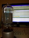
Example of a 'Tube':
20150202_210310a.jpg

This is an unused triode used in 275W audio amplifiers. Genuine article, probably a collectors item now, Audioguru's message in the background as proof it's real. It stands 300mm tall and is 90mm diameter. The heater alone consumes about 70W of power.

Brian.
 

I never progressed to the 813, the house was warm enough as it was. I did build lots of things with it's little brother, the 807 though.

I remember listening to a VERY strong 1.8MHz Morse signal in my youth that used to click all over the bands from MW up to about 10MHz. I tracked it down to a Radio Amateur about 10 miles away and called to warn them of the interference they were causing. The power limit on the band was (still is I think) 10W but they were running a PA with four 813s in parallel, all with anodes glowing cherry red which I would estimate produced around 1.5kW. It's no wonder their signal was strong!

That 4212H triode was used single ended in 275W PA systems and the one I have here is from the end of the production line. It has a directly heated cathode and carbon anode and although not a reject, has never had the getter rings ignited! It's very useful as an educational model because it's big enough to look down inside the anode and clearly see the electrode construction.

Brian.
 

That valve was not used on the Rediffusion wired TV system was it?. Its just that while I was in heavy test (1967/8?), some one was working on a huge rack which produced 1kW? of audio for the Rediffusion wired TV system. They supplied the TV vision down a balanced feeder which also fed the audio. One watt was allowed per subscriber which was fed directly to the loudspeaker via a pot. They were high efficiency loudspeakers though. The racks still had space in them for mercury arc rectifiers, though they had been changed over to silicon.
Frank
 

Almost certainly that is exactly where it came from!
My 'better half' gave it to me, her first husband died about 20 years ago but he was a senior technical person for Rediffusion and later "British Relay TV". I think it was presented to him at an award ceremony and she kept it after he passed away. It has never seen active service, the getter rings still have un-ignited magnesium in them!

I worked in TV in the 60s and 70s although not with wired systems, I did come across the occasional customer with a thousand wires poking out through their wall and boxes with a loudspeaker and many position switch though!

Brian.
 

Ah, yes, the dreaded S101. It was a two pole, 12way? switch that had just been put into consumers houses during my time with Redifusion. There were questions hanging over its reliabilty and with 1.25 million subscribers, it could have been a headache for them. I left Rediffusion central labs and went to the ITA (remember them?), stayed there the rest of my working life. I maintained TV transmitters, then joined to HQ to supply specialist services to the transmitter group. I ended up in my last ten years fiddling with telemetry systems. The ITA was always hot on telemetry, visitors were always amazed when we showed them our Crystal Palace transmitter which was unmanned, serving ten million Londoners, while the BBC next door was fully manned.
Frank
 

Status
Not open for further replies.

Part and Inventory Search

Welcome to EDABoard.com

Sponsor

Back
Top