LioTa
Newbie level 4
Hey.
I'm currently working on a project which consists in matching impedances in a transmission line composed of rectangular waveguides.
I'm working at 2.45E9 Hz in TE10 mode.
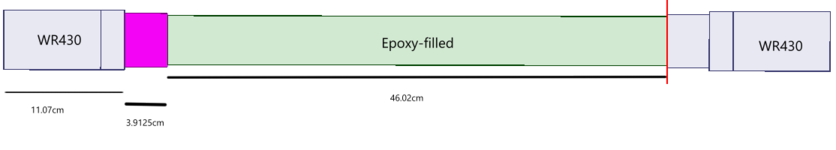
There is one WR430 to coax 430WCAN on each end of the line with a 50 ohms port. Then there is a waveguide that I had to determine that is used as a quarter lambda transformer between the WR430 and the rest of the line. In the middle of the line, there is a 10cm x 4.5cm rectangular waveguide filled with epoxy.
I have also added small sections to both the WR430 and the Epoxy-filled waveguide so that their lengths are odd multiples of 1/4lambda to avoid complex loads.
So I have calculated everything I needed (lambda, k, Beta, ...) and managed to determine that, in order to do the matching, I'd need the quarter lambda transformers to be 9.8cm x 4.9cm rectangular waveguide filled with air, which has a characteristic impedance of around 482.06 ohms (the characteristic impedance that I calculated was 483.05 ohms). With all of that, I simulate and I find VSWRs around 1.68, which isn't terrible(about -12dB S-parameters) but is still much worse than what I expected, considering I redid the calculations and found an impedance almost exactly equal to the WR430's characteristic impedance.
So, that's why I come here, to see if anyone knows what the problem might be. I've already checked if the imaginary part in the characteristic impedance of the Epoxy-filled wg was responsible for it and came to the conclusion that it barely changed anything(at least not enough for the VSWRs to be that far from the expected ones).
I've also checked the Betas in HFSS's solution data and found that the Epoxy filled wg's was quite different from the one I had calculated, as is its characteristic impedance for some reason and so I changed its length and obtained the results mentioned before.
Something weird about that is that I determined that for the characteristic impedance of the quarter wave transformers to even matter, the length of the Epoxy-filled wg would have to be an odd multiple of 1/4lambda, and 46.09cm is an even multiple of that lambda g (34* 1.53cm), yet it yields better results than the closest odd multiple of lambda g (35*1.53cm) so yeah I'm not sure why that is.
I'm currently working on a project which consists in matching impedances in a transmission line composed of rectangular waveguides.
I'm working at 2.45E9 Hz in TE10 mode.
There is one WR430 to coax 430WCAN on each end of the line with a 50 ohms port. Then there is a waveguide that I had to determine that is used as a quarter lambda transformer between the WR430 and the rest of the line. In the middle of the line, there is a 10cm x 4.5cm rectangular waveguide filled with epoxy.
I have also added small sections to both the WR430 and the Epoxy-filled waveguide so that their lengths are odd multiples of 1/4lambda to avoid complex loads.
So I have calculated everything I needed (lambda, k, Beta, ...) and managed to determine that, in order to do the matching, I'd need the quarter lambda transformers to be 9.8cm x 4.9cm rectangular waveguide filled with air, which has a characteristic impedance of around 482.06 ohms (the characteristic impedance that I calculated was 483.05 ohms). With all of that, I simulate and I find VSWRs around 1.68, which isn't terrible(about -12dB S-parameters) but is still much worse than what I expected, considering I redid the calculations and found an impedance almost exactly equal to the WR430's characteristic impedance.
So, that's why I come here, to see if anyone knows what the problem might be. I've already checked if the imaginary part in the characteristic impedance of the Epoxy-filled wg was responsible for it and came to the conclusion that it barely changed anything(at least not enough for the VSWRs to be that far from the expected ones).
I've also checked the Betas in HFSS's solution data and found that the Epoxy filled wg's was quite different from the one I had calculated, as is its characteristic impedance for some reason and so I changed its length and obtained the results mentioned before.
Something weird about that is that I determined that for the characteristic impedance of the quarter wave transformers to even matter, the length of the Epoxy-filled wg would have to be an odd multiple of 1/4lambda, and 46.09cm is an even multiple of that lambda g (34* 1.53cm), yet it yields better results than the closest odd multiple of lambda g (35*1.53cm) so yeah I'm not sure why that is.