Continue to Site

Welcome to EDAboard.com

Welcome to our site! EDAboard.com is an international Electronics Discussion Forum focused on EDA software, circuits, schematics, books, theory, papers, asic, pld, 8051, DSP, Network, RF, Analog Design, PCB, Service Manuals... and a whole lot more! To participate you need to register. Registration is free. Click here to register now.

Want to know operation of this Schematic

Status
Not open for further replies.
Hello Brad,

As i told you in my previous post i have tried to simulate this circuit on TINA simulator but i am not frequent user of this tool so couldnt simulate the circuit.

However, i have made few changes in circuit.

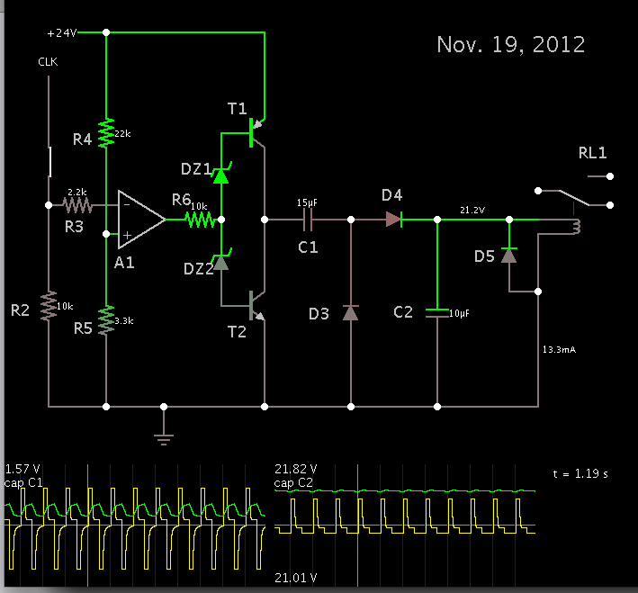
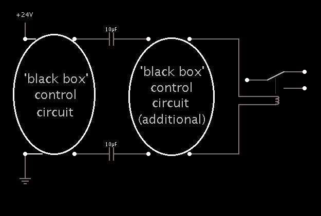
Our main goal is to design a circuit in sucha way that when any of the component get short or open relay should not energize (it should stay connected at NC position)

In this attached circuit I found following error, help to resolve this issue.

1) When R3 Short Relay energize
2) When R13 Short Relay energize
3) When R2 open Relay energize
4) When R11 open Relay energize
5) When R12 open Relay energize
6) When R13 open Relay energize
7) When C1 Short Relay energize
8) When C2 Short Relay energize
9) When C3 Open Relay energize
10) When DZ3 Short Relay energize
11) When T4(C-E) short Relay energize
12) When T4(B-C) short Relay energize
13) When outout of A2 op-amp short with inverting inverting input of A2 op-amp Relay energize

As per UL in above all condition relay should deenergize.

I am confuse what to do to resolve all this issues?

Is there any other way to resolve this issue by adding or subtracting few components from this circuit?

In this Circuit i have removed D4 & D5 because it doesnt affect the result, wheather its there or not.

Atleast circuit should resolve all those issues on any clock frequency and 24VDC voltage, i dont require tolerence in voltage range.

Look forward to hear from you soon.
 

Attachments

  • Final Falstad Script V2.1.txt
    3.1 KB · Views: 55

I have been running your latest schematic in simulation. Changing a few different component values. Rearranging a component here or there.

Some of the failure events are very unlikely. Example, resistors rarely short, since their construction has the resistive element physically separating the leads.

It is difficult enough to make a circuit work reliably. Now UL is asking you to make it shut off completely if any little thing goes wrong. However I suppose UL would say 'you need to make it impossible for fuel to flow unless every little thing is right.'

You must imagine various paths to solve this problem.

Consider whether you can simplify the project by eliminating excess components.

Or make the project more complicated by putting in more components to block current.

Consider this: Will putting 2 relays in series make it possible to satisfy the requirements? Because then each relay must be energized reliably. Two driver circuits, etc.

The two capacitors are a key feature. They are needed to separate the DC supply from the relay. It is only by sending AC pulses through the capacitors, that current can flow. And by rectifying the current. Can this process be made to operate only within a window of reliable performance? And below the window, or above the window, the relay is totally de-energized?

Etc.
 

Apologize for late response.

Did you able to solve any of the error which i have mentioned in #121? if yes kindly share updated script with me.

Yes i know its very difficult to satisfy each criteria of UL, UL is asking to shut off the device when any of the components fail.

Yes i am ready to eliminate excess component if we can solve above error(thats what i did by removing two diodes).

You are right two capacitors are heart of the circuit, and by the way its a concept of charge pump relay.

i am not getting your below sentence

"The two capacitors are a key feature. They are needed to separate the DC supply from the relay. It is only by sending AC pulses through the capacitors, that current can flow. And by rectifying the current. Can this process be made to operate only within a window of reliable performance? And below the window, or above the window, the relay is totally de-energized?"


You mean to say two parallel driver circuit and two relay in parallel?
 

i am not getting your below sentence

"The two capacitors are a key feature. They are needed to separate the DC supply from the relay. It is only by sending AC pulses through the capacitors, that current can flow. And by rectifying the current. Can this process be made to operate only within a window of reliable performance? And below the window, or above the window, the relay is totally de-energized?"

I guess I should have made the above idea separate and distinct from the following idea.

You mean to say two parallel driver circuit and two relay in parallel?

The idea of installing an additional driver or relay, is only a brainstorm. It follows the logic that by adding more devices in series, we make it necessary for more things to have to go right, in order for the relay contacts to close.

I'm not saying it's the only logic to follow.

Did you able to solve any of the error which i have mentioned in #121? if yes kindly share updated script with me.

There's also the logic that says to simplify operation. Use fewer devices. Consequently each device is more vital to proper operation. (This follows a reverse logic from the above.)

So...

I deleted the right half of the driver circuit. Then I added a Villard voltage doubler.


It may be worth a try. The layout is encoded in the attachment below.
 

Attachments

  • relay-driver-Nov19-2012.txt
    1.8 KB · Views: 61

I guess I should have made the above idea separate and distinct from the following idea

Could you please elaborate more on this idea it looks interesting, could you describe by schematic or falstad script?


The idea of installing an additional driver or relay, is only a brainstorm. It follows the logic that by adding more devices in series, we make it necessary for more things to have to go right, in order for the relay contacts to close.
I'm not saying it's the only logic to follow..


I am interested to know about this logic.


There's also the logic that says to simplify operation. Use fewer devices. Consequently each device is more vital to proper operation. (This follows a reverse logic from the above.)

So...

I deleted the right half of the driver circuit. Then I added a Villard voltage doubler.


It may be worth a try. The layout is encoded in the attachment below.

Yes its a good logic you have eliminated many components, and its operate very well, what effects happen after eliminating those components? you removed one op-amp and peripheral circuit does it affect on performance?

Even i have tried to simulate this script on my end and i found following result,
When C2 gets open chattering happen, if we can resolve this problem then this circuit might satisfy UL standard
 

When C2 gets open chattering happen,
Put another similar capacitor, in parallel to C2


Is your relay fail safe and it cannot stuck in on position.
 

When C2 gets open chattering happen, if we can resolve this problem then this circuit might satisfy UL standard

As ALERTLINKS recommends, a second capacitor in parallel will serve as a backup.

Could you please elaborate more on this idea it looks interesting, could you describe by schematic or falstad script?

As a safeguard there ought to be one or more capacitors between the relay and the power supply. Capacitors block DC, so that no current can get to the relay in the Off state.

The challenge is to create a 'black box' which will operate on the capacitors somehow, to permit a certain amount of current to get to the relay.


The black box needs to obey certain rules.

It is a matter of applying the right concepts, and assembling the right components in the black box, or boxes, to do the job.

Yes its a good logic you have eliminated many components, and its operate very well, what effects happen after eliminating those components? you removed one op-amp and peripheral circuit does it affect on performance?

The Villard doubler is an alternate configuration to the symmetrical concept used until now (known as the Greinacher doubler). The comparator section was optional.

I don't know that this new arrangement will pass the fault mode analysis.

Notice that it has a direct connection to the power supply ground. This may or may not be permitted by UL standards.
 

As ALERTLINKS recommends, a second capacitor in parallel will serve as a backup..

Yes Alertlinks right second capacitor serve as backup, but as per UL when any component gets open or short relay should turn off, have a look on attached picture for more information

As a safeguard there ought to be one or more capacitors between the relay and the power supply. Capacitors block DC, so that no current can get to the relay in the Off state.

The challenge is to create a 'black box' which will operate on the capacitors somehow, to permit a certain amount of current to get to the relay.


The black box needs to obey certain rules.

It is a matter of applying the right concepts, and assembling the right components in the black box, or boxes, to do the job.

Yes its possible but circuit gets more complicated i guess, whats your opinion on this?

The Villard doubler is an alternate configuration to the symmetrical concept used until now (known as the Greinacher doubler). The comparator section was optional.

I don't know that this new arrangement will pass the fault mode analysis.

Notice that it has a direct connection to the power supply ground. This may or may not be permitted by UL standards.

Greinacher doubler is suitable circuit as per our requirement, but we need to resolve that one error when C2 gets open relay should not chatter but it should turn OFF, i think in previous circuit scenario was the same direct connection to the power supply ground. but i will ask UL regarding this.
 

Attachments

  • with parallel capacitor.jpg
    with parallel capacitor.jpg
    96.4 KB · Views: 56
  • without parallel capacitor.jpg
    without parallel capacitor.jpg
    84.9 KB · Views: 67

C2 is a smoothing capacitor.

It will be a new challenge to detect the absence of a smoothing capacitor, and force a shutdown.

There's a chance it isn't even needed in a real live circuit. Hence I believe if C2 goes open, the relay would continue to stay closed. It would receive rapid DC pulses.

A real relay can chatter only when it gets a slow frequency of pulses, say a few dozen Hz.

At 1000 Hz it cannot chatter, or toggle. I wonder if UL takes this into account. Perhaps they must follow some criteria I am not aware of.

This is a situation that requires testing with real components.
 

Status
Not open for further replies.

Similar threads

Part and Inventory Search

Welcome to EDABoard.com

Sponsor

Back
Top