Continue to Site

Welcome to EDAboard.com

Welcome to our site! EDAboard.com is an international Electronics Discussion Forum focused on EDA software, circuits, schematics, books, theory, papers, asic, pld, 8051, DSP, Network, RF, Analog Design, PCB, Service Manuals... and a whole lot more! To participate you need to register. Registration is free. Click here to register now.

[SOLVED] voltage to frequency conversion

Status
Not open for further replies.

anj

Member level 3
Member level 3
Joined
Aug 16, 2012
Messages
66
Helped
7
Reputation
14
Reaction score
7
Trophy points
1,288
Location
Rajkot, Gujarat, India
Activity points
1,679
hello all..
I want to convert voltage to frequency by means of any IC.
right now I am using LM331 but not getting any required output.
I can post my circuit too if anybody wants..
thanks in advance...
please suggest any reliable circuit/IC/other option..
 

hello all..
I want to convert voltage to frequency by means of any IC.
right now I am using LM331 but not getting any required output.
Hi!
Is It an experiment in telepathy ? Specify your requirements.
 
thanks pplus for reply.. :smile:
I want to convert maximum 20V (AC) to a certain amount of frequency so, which can be measured with a micro controller.
It's like Analog to Digital Conversion task.
 

And why you not satisfied LM311?
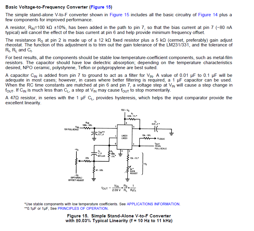
6642993300_1366866267.png
 
  • Like
Reactions: anj

    anj

    Points: 2
    Helpful Answer Positive Rating
The above chip & circuit is good...you can also use RC4152, besides other V-F IC's are also available.
 

The above chip & circuit is good...you can also use RC4152, besides other V-F IC's are also available.
thanks arunava 7

And why you not satisfied LM311?
thanks pplus.. :smile:
I am using the same circuit and
I am confused a bit about output pulse train's voltage levels my doubts:

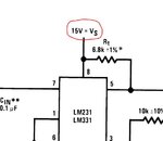
1) can Vs(pin 8) be 5 volt instead of 15 volt??
2) can I give this output(pin 3) pulse train directly to micro controller or not?? or I have to use switching transistor at output??

thanks again
ANJ
 

1) can Vs(pin 8) be 5 volt instead of 15 volt??
LM311 operates on single 5V Supply
2) can I give this output(pin 3) pulse train directly to micro controller or not?? or I have to use switching transistor at output
Yes, it is open collector. Simply connect pull-up resistor to supply uC.
 
  • Like
Reactions: anj

    anj

    Points: 2
    Helpful Answer Positive Rating
Thanks... :smile:
DOUBT.JPG
but in circuit it is written 15 volt.. why??
I am doing struggle since one week to get proper output..
thanks for giving your time..
 

I don't exactly understand the references to LM311 (comparator). No LM311 circuit has been shown in the thread.

Most of your questions are answered in the LM331 datasheet, e.g. power supply range (4.5 to 20V). 15V is just the voltage used in the reference design.

I presume you know the LM331 input voltage has to be positive DC voltage. So you can't measure AC voltage without conversion (rectifier circuit).
 
  • Like
Reactions: tpetar and anj

    anj

    Points: 2
    Helpful Answer Positive Rating

    tpetar

    Points: 2
    Helpful Answer Positive Rating
  • Like
Reactions: anj

    anj

    Points: 2
    Helpful Answer Positive Rating
thanks to Pplus , FvM and Bradtherad :smile:
classical solution provided by Pplus is good.
typo was seen by me too.. but I assume to be mum.

I presume you know the LM331 input voltage has to be positive DC voltage. So you can't measure AC voltage without conversion (rectifier circuit).
oops.. I am giving 12V AC to IC and struggling to get output.
to be frank I found datasheets of ICs very complicated besides my knowledge there is hard to find what I want.. thanks to everyone
I will learn to read datasheets in better way :wink:
 

Hello experts....
I am giving VS = 15 volt
and INPUT to VFC is now positive DC voltage through a potentiometer (for trial purpose)
but as soon as full scale voltage is given frequency goes zero..
I m getting frequencies for 10.5 volts as input... but then after it gets dead..
I am using same circuit as shown in post #4 by Pplus...
any suggestion or idea.. what could be possible cause??
 

**broken link removed**
The timing function consists of an RS flip-flop and a timer comparator connected to the external RtCt network.
When the input comparator detects a voltage at pin 7 higher than pin 6, it sets the RS flip-flop which turns ON the
current switch and the output driver transistor. When the voltage at pin 5 rises to ⅔ VCC, the timer comparator
causes the RS flip-flop to reset. The reset transistor is then turned ON and the current switch is turned OFF.
However, if the input comparator still detects pin 7 higher than pin 6 when pin 5 crosses ⅔ VCC, the flip-flop will
not be reset, and the current at pin 1 will continue to flow, trying to make the voltage at pin 6 higher than pin 7.
This condition will usually apply under start-up conditions or in the case of an overload voltage at signal input.
During this sort of overload the output frequency will be 0. As soon as the signal is restored to the working range,
the output frequency will be resumed.
 

Attachments

  • lm331.pdf
    805.6 KB · Views: 126
Last edited:
  • Like
Reactions: anj

    anj

    Points: 2
    Helpful Answer Positive Rating
What is voltage domain of a signal.. I know a signal has time and frequency domain but what is voltage domain and how is it different from time and frequency domain and also why do we need to represent a signal in time and frequency domain? In VCO based ADC is it described that the input voltage signal is converted to time domain to obtain timing information.. why do we need to convert voltage to time domain.. I wont the voltage(sin wave) itself have timing information... what is the difference??? could anyone please show me the images of the signal in all the 3 domains?
 
Last edited:

Status
Not open for further replies.

Part and Inventory Search

Welcome to EDABoard.com

Sponsor

Back
Top